
Magnetic wall decoupling method for monopole coil array in ultrahigh field MRI: a feasibility test
Introduction
Ultrahigh field (UHF) MRI is able to provide a high signal-noise-ratio (SNR) and a high contrast for human imaging (1-8). However, attenuation of radiofrequency (RF) signals increases at higher frequencies, which could degrade the sensitivity in the deep area of the high dielectric, conductive biological samples, such as human body (9). To increase the SNR gain in the area located deep inside the human head or body, radiative coil arrays including dipole (10,11) and monopole (12,13) arrays have been proposed for UHF MRI applications, showing better SNR performance in the deep area (10,13).
Reducing the electromagnetic (EM) coupling among coil elements is critical to the coil array designs, given that better decoupling performance usually means higher SNR and better parallel imaging ability (8,14-19). Several methods are widely employed to reduce the mutual EM coupling of coil elements including the use of low input impedance preamplifiers, overlapping of adjacent loop elements (20), transformers (21) and L/C decoupling networks (22-28). However, the traditional methods, such as element overlapping and L/C decoupling network, face challenges and are not readily feasible for dipole or monopole transceiver arrays. A new decoupling method based on induced current elimination (ICE) or magnetic wall technique has recently been proposed and has demonstrated its feasibility in designing microstrip transmission line (MTL) arrays (29-32) and traditional L/C loop arrays (33-35). The magnetic wall decoupling method uses an independent decoupling element which forms a metamaterial to eliminate the current induced by EM coupling. This method is more general and does not need physical connection between coil elements, which is essential for dipole and monopole transceiver arrays.
In this study, we aim to test the feasibility and investigate the performance of the ICE/magnetic wall decoupling method for the monopole array (13). A two-channel ICE-decoupled monopole array was designed and fabricated for MR imaging at 7 T. In the array, an L-shaped capacitive network was employed to address the impedance mismatch of monopole elements, an issue currently faced in monopole RF coil designs. Bench test and MR imaging results obtained from the ICE-decoupled array demonstrate its capability of obtaining a high decoupling between monopole elements while original B1 profiles of the individual monopole elements are maintained. To further validate the ICE/magnetic wall decoupling method in monopole arrays, Q values, S parameters, B1+ maps, phantom images and SNR maps of the ICE-decoupled monopole elements were evaluated and compared with the monopole elements without decoupling methods. Additionally, full-wave EM simulations were applied to analyze the proposed design. Simulated B1+ maps and gradient recalled echo (GRE) images were compared with experimental results.
Materials and methods
Design and construction of the two-channel ICE-decoupled monopole array
For the two monopole elements without decoupling methods (as shown in Figure 1A), the S11 of each monopole element could still achieve about –12 dB even no matching circuits was employed (13). However, the S11 of each monopole element was only about –2 dB when the decoupling element was added in practice. This was because the self-impendence of each monopole element was totally changed by the decoupling element. Therefore, matching circuits had to be employed for the ICE-decoupled monopole elements. An L-shaped capacitive network (Cs and Cp, as shown in Figure 1B and 1C) were chosen as the matching circuit considering that trimmer capacitors were easier to be obtained. To make a fair comparison, the matching circuit was also applied for the two monopole elements without decoupling methods (Figure 1B). To compensate the induced capacitance of Cs, the length of the matched monopole elements was a little longer (about 25 cm) than unmatched monopole elements (about 20 cm) (13). The series capacitor Cs could also be used to finely tune the resonant frequency of the monopole elements.

Two monopole elements with and without the decoupling element were mounted on a cylindrical acrylic former with an outer diameter of 26 cm, as shown in Figure 2A and 2B. The distance of the two elements were 8 cm and the decoupling element was symmetrically placed between them. All conductor strips were made of the copper tape (3M, St, Paul, MN) with a thickness of 100 µm and a width of 10 mm. The length of monopole elements and the decoupling element were about 25 cm. Two capacitors Cs and Cp (Johanson Manufacturing corp., NJ, USA) were applied for matching and finely tuning. For the two ICE-decoupled monopole elements, a monopole series with a capacitor (referred to as the decoupling capacitor Cd) was served as the decoupling element, as shown in Figure 1C and Figure 2B. The upper corners of the ground plate, which had a dimension of 40×40 cm2, were cut to fit in our MRI bore. To reduce the eddy currents, the ground plate was cut by a number of slots and chip capacitors with a value of 1 nF were connected across slots. A cylindrical water phantom with an outer diameter of 16 cm and a length of 37 cm was placed 2 cm below the monopole elements. The electromagnetic parameters of the water phantom were measured by a dielectric probe (DAK-12, Speag, Switzerland): conductivity σ =0.59 s/m; relative permittivity εr =78.

Bench tests and MR imaging experiments
The magnetic wall decoupling method for the monopole array was validated by bench tests and MR imaging experiments on the water phantom. All MRI experiments were performed on a whole-body MRI scanner (7 T MAGNETOM, Siemens Healthcare, Erlangen, Germany). Reflection coefficient (S11) and transmission coefficient (S21) of the two monopole elements with and without the decoupling method were measured with an Agilent E5071C network analyzer. The reflection coefficient measurements were also used to calculate the coil’s unloaded Q value (QUL) and loaded Q value (QL).
To demonstrate the decoupling performance of the magnetic wall decoupling method, B1+ maps and image profiles of the water phantom in the transverse plane using the two monopole elements with and without the decoupling element were compared. The transverse plane chosen for MR imaging was 4 cm apart from the GND. During the MR imaging experiments, one monopole element was used for both transmit and receive with the other one terminated with 50 Ω load. The sequence and parameters used for imaging acquisition were GRE, flip angle (FA) =25 deg, TR =150 ms, TE =20 ms, field of view (FOV) =180×180 mm2, matrix =256×256, slice thickness =5 mm, bandwidth =260 Hz/pixel, and phase encoding is in the y direction. In this comparison, the experimental setup, including imaging sequence and parameters, was exactly the same. SNR maps were generated by dividing the signal intensities (SI) of the images by the standard deviation (SD) of the noise (36): SNR= SI⁄SD ×0.66. The B1+ map was measured with a Turbo FLASH method and scaled to angle (37,38). During B1+ map measurement, all parameters were set the same for quantitative comparisons.
EM simulations
The three dimensional (3-D) EM and RF circuit co-simulation approach was used to investigate the performance of the magnetic wall decoupling method for the monopole array (28,32,39-41). Full-wave EM modeling (HFSS, ANSYS, Canonsburg, PA, US) was chosen as the EM simulation tool because of its fast speed (42).
Two monopole elements with and without the decoupling element were modeled in HFSS for simulation, as shown in Figure 3A and 3B. In the simulation, all parameters including dimensions of the coil and phantom, electromagnetic parameters and position of the phantom were exactly the same with the practical situation. The distance of the boundary and monopole elements was larger than λ/2. Manual mesh was used to accelerate simulation convergence and the convergence condition ∆S was set to 0.002 to achieve more reliable results. In the simulation, one port was excited with 1 W with the other port terminated with 50 Ω. B1 maps (transmission field B1+ and reception field B1–) were extracted from simulation by Eq. [1] (43). Image or SI profiles of each coil element were calculated from simulation by Eq. [2] (44).

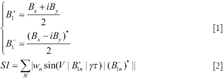
where N is the total number of the voxels within the FOV; γ denotes the gyromagnetic ratio; Wn is the water content percentage of the nth voxel, and τ is the excitation duration. V, the normalization factor, is determined by: , where α is the flip angle.
Results
Measured S parameters and Q values
For two monopole elements without matching circuits and without the decoupling element, the measured reflection coefficients (S11) loaded with the water phantom were only –12.7 dB, as shown in Figure 4A. The S11 of the monopole element could be improved to better than –28 dB when the L-shaped matching circuit was added, as shown in Figure 4B and 4C. This indicated the impedance could be well matched to 50 Ω by using the proposed matching circuit. The impedance was closer to 50 Ω, indicating that the noise figure (NF) of the conventional 50 Ω preamplifier was better and the SNR could be improved by using the matching circuit.

For the two monopole elements without the decoupling method, the transmission coefficient S21 between the two coil elements was about –10 dB, as shown in Figure 5A. The average QUL and QL of a single element were about 9.3 and 3.8, respectively.

For the ICE-decoupled two monopole elements, the transmission coefficient S21 between the two coil elements was about –32 dB, as shown in Figure 5B. This means the coupling of two monopoles can be well reduced by using ICE/magnetic wall decoupling method. The average QUL and QL of a single element were 18 and 6.2, respectively. The increased Q value is probably because of the better decoupling performance and the shielding effect of the decoupling element. The improved QL could also be observed clearly from the comparison of S11 plots in Figure 4B and 4C.
B1 maps, MR images and SNR maps
Measured and simulated B1+ maps of the two monopole elements without and with the decoupling element were shown in Figure 6A and 6B. For both measured and simulated results, B1+ map of each channel of the ICE-decoupled array was more independent and weaker at the neighborhood of the two elements, indicating better decoupling performance was obtained by the ICE/magnetic wall decoupling method. From the measured results, the average angles, which were corresponding to average B1+, of the neighborhood (red circle area in Figure 6A) were reduced from 33 degree to 17 degree and from 21 degree to 9 degree for channel 1 and channel 2, respectively. In Figure 6A, the B1+ field of ICE-decoupled elements was stronger at the peripheral area of the water phantom, which was probably due to the shielding effect of the decoupling element.

Measured and calculated GRE images from simulation without and with the decoupling element were shown in Figure 6C and 6D. Well defined image profiles of the two ICE-decoupled monopole elements were obtained, indicating sufficient electromagnetic decoupling between the two elements. Note that nulls of the images of the ICE-decoupled elements at the peripheral area was because of the different distribution of the transmit field and receive field. The agreement between the simulation and experiment also demonstrated that the simulation results are reliable.
Measured SNR maps of the two monopole elements with and without the decoupling element were shown in Figure 6E. Two squares (gray squares in Figure 6E) with 15 pixels at the peripheral and center areas were chosen for the quantitative comparison of the SNR. The ICE-decoupled elements had better SNR at the peripheral area with an improvement of about 15% and meanwhile kept similar SNR at the center area of the phantom. This improvement can be verified by the comparison of B1+ map as described above and was consistent with the previous work (33,35).
Discussion and conclusions
In this study, the feasibility of ICE/magnetic wall decoupling method for the monopole radiative coil array has been validated through bench tests, MR imaging experiments and EM simulations. With this decoupling technique, coupling between two monopole elements is able to be reduced from about –10 dB to a sufficiently small value (better than –30 dB). Due to the better decoupling performance and shielding effect of the decoupling element, the ICE-decoupled monopole elements demonstrate more independent image profiles and achieve a higher SNR at the peripheral area of the water phantom over the monopole array without decoupling treatment.
Additionally, an L-shaped capacitive matching circuit for the monopole element is proposed and investigated, showing a significant improvement of the reflection coefficients S11 (from –12.7 to –28 dB). Better impedance matching could result in increased transmit efficiency, higher SNR, and decreased NF of the conventional 50 Ω preamplifier. Therefore this design can be expected to have a possible transmit power reduction and the SNR improvement over the monopole elements without matching circuits.
Although the ICE/magnetic wall decoupling method is validated for only the monopole array in this work, this decoupling method is more general and should be suitable for other kinds of radiative arrays, e.g., dipole coil arrays. This study has paved the way for designing ICE-decoupled multi-channel volume-typed radiative array for human MR imaging.
Acknowledgements
The authors would like to thank Jan Pedersen, Lei Shi and Zhongwei Chen from Institute of Biophysics, Chinese academy of sciences for their technical assistance. This work was supported in part by Chinese National Major Scientific Equipment R&D Project (grant number ZDYZ2010-2), the Ministry of Science and Technology (MOST) of China (grant number 2012CB825500), the MOST Innovation Method Program (grant number 2009IM030900), Chinese Academy of Sciences Strategic Priority Research Program (grant number XDB02010001, XDB02050001), and National Natural Science Foundation of China Grant 51228702.
Author contribution: Conceived and designed the study: Xinqiang Yan, Xiaoliang Zhang; performed the experiments and collected data: Xinqiang Yan; analyzed the data: Xinqiang Yan, Xiaoliang Zhang; contributed materials/analysis tools: Long Wei, Rong Xue; wrote the paper: Xinqiang Yan, Xiaoliang Zhang, Rong Xue.
Disclosure: The authors declare no conflict of interest.
References
- Vaughan JT, Garwood M, Collins CM, et al. 7T vs. 4T: RF power, homogeneity, and signal-to-noise comparison in head images. Magn Reson Med 2001;46:24-30. [PubMed]
- Yacoub E, Shmuel A, Pfeuffer J, et al. Imaging brain function in humans at 7 Tesla. Magn Reson Med 2001;45:588-94. [PubMed]
- Zhu XH, Zhang Y, Tian RX, et al. Development of (17)O NMR approach for fast imaging of cerebral metabolic rate of oxygen in rat brain at high field. Proc Natl Acad Sci U S A 2002;99:13194-9. [PubMed]
- Lei H, Zhu XH, Zhang XL, et al. In vivo 31P magnetic resonance spectroscopy of human brain at 7 T: an initial experience. Magn Reson Med 2003;49:199-205. [PubMed]
- Zhang X, Ugurbil K, Chen W. Microstrip RF surface coil design for extremely high-field MRI and spectroscopy. Magn Reson Med 2001;46:443-50. [PubMed]
- Zhang X, Zhu XH, Chen W. Higher-order harmonic transmission-line RF coil design for MR applications. Magn Reson Med 2005;53:1234-9. [PubMed]
- Zhang X, Ugurbil K, Sainati R, et al. An inverted-microstrip resonator for human head proton MR imaging at 7 tesla. IEEE Trans Biomed Eng 2005;52:495-504. [PubMed]
- Adriany G, Van de Moortele PF, Wiesinger F, et al. Transmit and receive transmission line arrays for 7 Tesla parallel imaging. Magn Reson Med 2005;53:434-45. [PubMed]
- Collins CM, Yang QX, Wang JH, et al. Different excitation and reception distributions with a single-loop transmit-receive surface coil near a head-sized spherical phantom at 300 MHz. Magn Reson Med 2002;47:1026-8. [PubMed]
- Raaijmakers AJ, Ipek O, Klomp DW, et al. Design of a radiative surface coil array element at 7 T: the single-side adapted dipole antenna. Magn Reson Med 2011;66:1488-97. [PubMed]
- Wiggins GC, Zhang B, Lattanzi R, et al. The Electric Dipole Array: An Attempt to Match the Ideal Current Pattern for Central SNR at 7 Tesla. Proc Intl Soc Mag Reson Med 2012;20:541.
- Geschewski FH, Brenner D, Felder J, et al. Optimum coupling and multimode excitation of traveling-waves in a whole-body 9.4T scanner. Magn Reson Med 2013;69:1805-12. [PubMed]
- Hong SM, Park JH, Woo MK, et al. New design concept of monopole antenna array for UHF 7T MRI. Magn Reson Med 2014;71:1944-52. [PubMed]
- Sodickson DK, Manning WJ. Simultaneous acquisition of spatial harmonics (SMASH): fast imaging with radiofrequency coil arrays. Magn Reson Med 1997;38:591-603. [PubMed]
- Pruessmann KP, Weiger M, Scheidegger MB, et al. SENSE: sensitivity encoding for fast MRI. Magn Reson Med 1999;42:952-62. [PubMed]
- Griswold MA, Jakob PM, Heidemann RM, et al. Generalized autocalibrating partially parallel acquisitions (GRAPPA). Magn Reson Med 2002;47:1202-10. [PubMed]
- Pang Y, Vigneron DB, Zhang X. Parallel traveling-wave MRI: a feasibility study. Magn Reson Med 2012;67:965-78. [PubMed]
- Wu B, Wang C, Lu J, et al. Multi-channel microstrip transceiver arrays using harmonics for high field MR imaging in humans. IEEE Trans Med Imaging 2012;31:183-91. [PubMed]
- Wu B, Zhang X, Wang C, et al. Flexible transceiver array for ultrahigh field human MR imaging. Magn Reson Med 2012;68:1332-8. [PubMed]
- Roemer PB, Edelstein WA, Hayes CE, et al. The NMR phased array. Magn Reson Med 1990;16:192-225. [PubMed]
- Avdievich NI. Transceiver-Phased Arrays for Human Brain Studies at 7 T. Appl Magn Reson 2011;41:483-506. [PubMed]
- Pinkerton RG, Barberi EA, Menon RS. Transceive surface coil array for magnetic resonance imaging of the human brain at 4 T. Magn Reson Med 2005;54:499-503. [PubMed]
- Wu B, Zhang X, Qu P, et al. Design of an inductively decoupled microstrip array at 9.4 T. J Magn Reson 2006;182:126-32. [PubMed]
- Wu B, Qu P, Wang C, et al. Interconnecting L/C components for decoupling and its application to low-field open MRI array. Concepts Magn Reson 31B:116-26.
- Wu B, Zhang X, Qu P, et al. Capacitively decoupled tunable loop microstrip (TLM) array at 7 T. Magn Reson Imaging 2007;25:418-24. [PubMed]
- Wu B, Wang C, Krug R, et al. 7T human spine imaging arrays with adjustable inductive decoupling. IEEE Trans Biomed Eng 2010;57:397-403. [PubMed]
- Zuo Z, Park J, Li Y, et al. An Elliptical Octagonal Phased-Array Head Coil for Multi-Channel Transmission and Reception at 7T. Proceedings 20th Scientific Meeting Proc Intl Soc Mag Reson Med 2012;20:2804.
- Yan X, Ma C, Shi L, et al. Optimization of an 8-Channel Loop-Array Coil for a 7 T MRI System with the Guidance of a Co-Simulation Approach. Applied Magnetic Resonance 2014;45:437-49.
- Xie Z, Zhang X. A novel decoupling technique for non-overlapped microstrip array coil at 7T MR imaging. Proc Intl Soc Mag Reson Med 2008;16:1068.
- Xie Z, Zhang X. An eigenvalue/eigenvector analysis of decoupling methods and its application at 7T MR imaging. Proc Intl Soc Mag Reson Med 2008;16:2972.
- Li Y, Xie Z, Pang Y, et al. ICE decoupling technique for RF coil array designs. Med Phys 2011;38:4086-93. [PubMed]
- Yan X, Zhang X, Ma C, et al. Optimization of B1 field homogeneity along the longitudinal direction for 7T MTL resonators by using a multi-row design. Proceedings 22th Scientific Meeting. Proc Intl Soc Mag Reson Med 2014;22:1309.
- Yan X, Zhang X, Feng B, et al. 7T transmit/receive arrays using ICE decoupling for human head MR imaging. IEEE Trans Med Imaging 2014. [Epub ahead of print]. [PubMed]
- Yan X, Zhang X, Ma C, et al. An eight-channel transmit/receive phased-array head coil with an ICE decoupling method at 7T. Proceedings 22th Scientific Meeting Proc Intl Soc Mag Reson Med 2014;22:1322.
- Yan X, Zhang X, Ma C, et al. Evaluation of ICE and capacitive decoupling methods using in 8-channel loop array coils at 7T. Proceedings 22th Scientific Meeting Proc Intl Soc Mag Reson Med 2014;22:1306.
- NEMA Standards Publication MS 1-2008. Determination of signal-to-noise ratio (SNR) in diagnostic magnetic resonance imaging. National Electrical Manufacturers Association 2008.
- Klose U. Mapping of the radio frequency magnetic field with a MR snapshot FLASH technique. Med Phys 1992;19:1099-104. [PubMed]
- Yarnykh VL. Actual flip-angle imaging in the pulsed steady state: a method for rapid three-dimensional mapping of the transmitted radiofrequency field. Magn Reson Med 2007;57:192-200. [PubMed]
- Kozlov M, Turner R. Fast MRI coil analysis based on 3-D electromagnetic and RF circuit co-simulation. J Magn Reson 2009;200:147-52. [PubMed]
- Yan X, Shi L, Wei L, et al. A hybrid sodium/proton double-resonant transceiver array for 9.4T MRI. IEEE MTT-S International Microwave Workshop Series on RF and Wireless Technologies for Biomedical and Healthcare Applications (IMWS-BIO) 2013.
- Yan X, Shi L, Zhuo Y, et al. Optimized MTL array with serial capacitors for 7T MRI. IEEE International Conference on Medical Imaging Physics and Engineering (ICMIPE) 2013. Shenyang, China. IEEE Catalog Number: CFP1373U-CDR ISBN: 978-1-4673-6013-5.
- Kozlov M, Turner R. A Comparison of Ansoft HFSS and CST Microwave Studio Simulation Software for Multi-channel Coil Design and SAR Estimation at 7T MRI. PIERS Online 2010;6:395:9.
- Hoult DI. The principle of reciprocity in signal strength calculations—A mathematical guide. Concepts Magn Reson 2000;12:173-87.
- Collins CM, Smith MB. Signal-to-noise ratio and absorbed power as functions of main magnetic field strength, and definition of “90 degrees” RF pulse for the head in the birdcage coil. Magn Reson Med 2001;45:684-91. [PubMed]

