
Decoupling and matching network for monopole antenna arrays in ultrahigh field MRI
Introduction
Ultrahigh field (i.e., 7 T and higher) MRI could provide a higher signal-to-noise ratio (SNR), better image resolution, and improved image contrast (1-3). As the Larmor frequency increases with magnetic field strength, the resultant high frequency at ultrahigh magnetic fields makes the design of large-sized radio-frequency (RF) coils challenging. To address this problem, a variety of RF coil arrays have been proposed and developed, including the L/C loop arrays (4-6), microstrip transmission line arrays (7-12) and radiative arrays (13-18). Among them, radiative coil arrays, e.g., dipole or monopole arrays, demonstrate their unique performance in design simplicity and large imaging penetration and coverage, and are increasingly used for ultrahigh field MRI.
Minimizing the electromagnetic (EM) coupling among coil elements is critical to RF coil array designs, given that better decoupling could lead to higher SNR and better parallel imaging performance. In telecommunication applications, a large amount of studies have been focused on reducing the coupling of monopole and dipole antennas. In references (19,20), different kinds of metamaterials were applied to decouple two nearby monopoles. Above from that, hybrid couplers using L/C network or microstrip line approach (21,22) have been used to achieve port decoupling for monopole or dipole antennas. All these methods could suppress the coupling effect, but suffer from complicated structures and might not be suitable for MRI applications.
In reference (23), a decoupling structure using a phase shifter and a bridge capacitor was successfully implemented to diminish the coupling between two printed monopoles. In MRI applications, tunable decoupling networks are preferred since different imaging samples or loads might cause the change of mutual coupling, consequently the fine adjustment of decoupling circuit is often needed. Since phase shifters are not easy to adjust in practice, this approach might not be suitable in MRI applications. In this study, we proposed a combined decoupling and matching network (DMN) for radiative coil arrays in ultrahigh field MRI, providing a convenient approach to feed and decouple radiative RF arrays.
Methods
Figure 1 shows the circuit diagram of the proposed DMN for antenna arrays in MRI applications. The DMN was accomplished by an interconnecting reactive element (Xc), two parallel reactive elements (Xp), and two series reactive element (Xs). The reactive element is a capacitor or inductor in practice.

Since Xc affects the odd but not the even mode, it can be used to make the odd mode impedance approach to the even mode impedance. In some special cases where the coupling is totally reactive, the even and odd mode impedance at the new ports can be equal to each other, which means that the new ports are decoupled. In general cases, a more complex network, e.g., T-shaped or π-shaped network, is needed for decoupling (24). In this study, Xp was partly used to form a π-shaped network with Xc for port decoupling, and partly used to form an L-shaped network with Xs for port matching.
In order to verify the proposed design, a 2-channel monopole array with DMN is numerically computed using ANSYS HFSS, as shown in Figure 2. The width and length of each monopole element are 1 cm and 25 cm, respectively. The distance of the two monopole elements is about 6 cm. A cylindrical water phantom with an outer diameter of 16 cm and a length of 30 cm is placed 2 cm below the monopole elements. The EM parameters of the water phantom are set as follows: conductivity σ =0.59 s/m; relative permittivity; εr =78.

For comparison, we also simulated a 2-channel monopole array without decoupling treatments and a single monopole. Values of all reactive components were obtained by RF circuit co-simulation method (25,26). The operate frequency is 297.2 MHz, which is the Larmor frequency of our unitized 7T MRI scanner.
Results
Simulated S-parameter
Figure 3 depicts the frequency response of the magnitudes of the S-parameters, with S11 and S21 representing reflection and mutual coupling, respectively. The values of reactive components used are as follows: Xc =6.6 pF, Xs =13.5 pF, Xp =71.9 nH. Figure 3A,C show the S-parameter of two coupled monopoles. As can be noticed, mutual coupling between the monopoles is nearly −5 dB at desired frequency when both monopoles are matched. With the proposed DMNs, ports 1 and 2 are well decoupled (−24.8 dB) and matched to 50 ohm (Ω) simultaneously, as shown in Figure 3B,D. It is worth noting that the S11 bandwidth of decoupled monopoles is rather small. This is partly due to the changing self-impedance, and partly due to the changing radiation pattern of the monopoles.

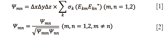
We also evaluated the normalized noise matrixes (Ψ) of the two arrays by calculating Eq. [1] and [2] (27), where Ekm is the local electric field of voxel k from channel m, σk is the local conductivity of voxel k, ∆x, ∆y and ∆z are the voxel size in x, y, and z directions. In this study, the voxel size for noise matrix calculation in x, y, z directions is 2, 2 and 5 mm, respectively. The noise correlation of the monopole arrays without decoupling treatments and with the proposed DMN are 0.41 and 0.15, respectively.
Current distribution
Figure 4 shows the current distribution of two monopole elements when only port 1 was excited with 1W power. Figure 4A shows the current distribution of the two close-spaced monopoles without decoupling treatments. Arrows in red color indicate the current directions along the monopole elements. It is obvious that the current flows into port 2 and the right monopole, leading to strong EM coupling between two ports. When the decoupling network was added, however, the induced current becomes almost zero at the feed-point of the right monopole, as shown in Figure 4B. This has also been validated by S-parameter results as described above.

From Figure 4B, it is also seen that not the monopole elements but the ports are decoupled. That means both monopole elements are excited when only one port is fed. The current distribution of the two-element array is characterized by “large” currents flowing in opposite directions. Similar results have also been observed in previous study (28).
Electronic and magnetic field distribution
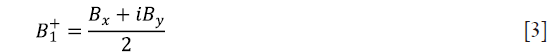
Figure 5 shows the H field, E field and transmit field (B1+) on the water phantom in the transverse plane of single monopole antennas (A1-A6), two coupled monopole antennas (B1-B6) and two decoupled monopole antennas (C1-C6). In the simulation, one port was excited with 1W with the other port terminated with 50 Ω. B1+ field was extracted from simulation by Eq. [3] (29).

As expected, part of the power was transferred to the other monopole element when no decoupling treatments were used, as shown in Figure 5A,B. The field result is consistent with the S21 result as described above (about −5 dB). It is worth noting that the electromagnetic fields of decoupled monopole elements are still different from that of single monopole even though the S21 is as low as −24.8 dB, as shown in Figure 5A,C. This also indicates that the proposed method is a port decoupling method rather than an element decoupling method.
Discussion and conclusions
In summary, by applying the proposed L/C network, the port isolation between two monopoles can be improved from −5 dB to −25 dB meanwhile excellent matching performance can also be attained. In the conventional approaches, decoupling network and matching network are separated which increases the circuit complexity. In this study, we utilized a combined DMN and thus the number of required components can be minimized. Since less number of tuning components is required, this design is advantageous to MRI applications.
It is noted that the proposed method is a port decoupling approach rather than an element decoupling approach. Therefore, the electric and magnetic fields of the decoupled monopole are different from those of single monopoles. This feature can be seen from Figure 4 that the two monopole elements with decoupling network have a similar current distribution as the loop coil, with currents on two conductors flow in different directions. This makes the H field and B1 field strong at the peripheral area on the phantom, as shown in Figures 5C1-C6.
Although this concept was exclusively presented for the particular case of a 2-channel monopole array, it can be generalized to monopole arrays with more channels, i.e., eight channels. Also, the idea can be extended to dipole arrays in MRI. In the case of the dipole antenna, the DMN might be different from the monopole antenna at certain level because of its enlarged self-impedance over that of the monopole antenna.
Acknowledgement
Funding: This study was supported in part by the National Natural Science Foundation of China Grant (51228702) and National Institutes of Health (NIH) R01EB008699.
Footnote
Conflicts of Interest: The authors have no conflicts of interest to declare.
References
- Yacoub E, Shmuel A, Pfeuffer J, Van De Moortele PF, Adriany G, Andersen P, Vaughan JT, Merkle H, Ugurbil K, Hu X. Imaging brain function in humans at 7 Tesla. Magn Reson Med 2001;45:588-94. [PubMed]
- Vaughan JT, Garwood M, Collins CM, Liu W, DelaBarre L, Adriany G, Andersen P, Merkle H, Goebel R, Smith MB, Ugurbil K. 7T vs. 4T: RF power, homogeneity, and signal-to-noise comparison in head images. Magn Reson Med 2001;46:24-30. [PubMed]
- Collins CM, Smith MB. Signal-to-noise ratio and absorbed power as functions of main magnetic field strength, and definition of “90 degrees” RF pulse for the head in the birdcage coil. Magn Reson Med 2001;45:684-91. [PubMed]
- Wiggins GC, Potthast A, Triantafyllou C, Wiggins CJ, Wald LL. Eight-channel phased array coil and detunable TEM volume coil for 7 T brain imaging. Magn Reson Med 2005;54:235-40. [PubMed]
- Avdievich NI. Transceiver-Phased Arrays for Human Brain Studies at 7 T. Appl Magn Reson 2011;41:483-506. [PubMed]
- Yan X, Zhang X, Feng B, Ma C, Wei L, Xue R. 7T transmit/receive arrays using ICE decoupling for human head MR imaging. IEEE Trans Med Imaging 2014;33:1781-7. [PubMed]
- Zhang X, Ugurbil K, Chen W. Microstrip RF surface coil design for extremely high-field MRI and spectroscopy. Magn Reson Med 2001;46:443-50. [PubMed]
- Zhang X, Ugurbil K, Sainati R, Chen W. An inverted-microstrip resonator for human head proton MR imaging at 7 tesla. IEEE Trans Biomed Eng 2005;52:495-504. [PubMed]
- Adriany G, Van de Moortele PF, Wiesinger F, Moeller S, Strupp JP, Andersen P, Snyder C, Zhang X, Chen W, Pruessmann KP, Boesiger P, Vaughan T, Uğurbil K. Transmit and receive transmission line arrays for 7 Tesla parallel imaging. Magn Reson Med 2005;53:434-45. [PubMed]
- Jasiński K, Młynarczyk A, Latta P, Volotovskyy V, Węglarz WP, Tomanek B. A volume microstrip RF coil for MRI microscopy. Magn Reson Imaging 2012;30:70-7. [PubMed]
- Metzger GJ, Snyder C, Akgun C, Vaughan T, Ugurbil K, Van de Moortele PF. Local B1+ shimming for prostate imaging with transceiver arrays at 7T based on subject-dependent transmit phase measurements. Magn Reson Med 2008;59:396-409. [PubMed]
- Yan X, Pedersen J, Wei L, Zhang X, Xue R. Multi-channel double-row transmission line array for human MR imaging at ultrahigh fields. IEEE Trans Biomed Eng 2015;62:1652-59. [PubMed]
- Raaijmakers AJ, Ipek O, Klomp DW, Possanzini C, Harvey PR, Lagendijk JJ, van den Berg CA. Design of a radiative surface coil array element at 7 T: the single-side adapted dipole antenna. Magn Reson Med 2011;66:1488-97. [PubMed]
- Hong SM, Park JH, Woo MK, Kim YB, Cho ZH. New design concept of monopole antenna array for UHF 7T MRI. Magn Reson Med 2014;71:1944-52. [PubMed]
- Yan X, Xue R, Zhang X. A monopole/loop dual-tuned RF coil for ultrahigh field MRI. Quant Imaging Med Surg 2014;4:225-31. [PubMed]
- Yan X, Zhang X, Wei L, Xue R. Magnetic wall decoupling method for monopole coil array in ultrahigh field MRI: a feasibility test. Quant Imaging Med Surg 2014;4:79-86. [PubMed]
- Yan X, Wei L, Xue R, Zhang X. Hybrid monopole/loop coil array for human head MR imaging at 7T. Appl Magn Reson 2015;46:541-50. [PubMed]
- Yan X, Zhang X, Wei L, Xue R. Design and Test of Magnetic Wall Decoupling for Dipole Transmit/Receive Array for MR Imaging at the Ultrahigh Field of 7T. Appl Magn Reson 2015;46:59-66.
- Ferrer PJ, González-Arbesú JM, Romeu J. Decorrelation of two closely spaced antennas with a metamaterial AMC surface. Microw Opt Technol Lett 2008;50:1414-7.
- Bait-Suwailam MM, Boybay MS, Ramahi OM. Electromagnetic Coupling Reduction in High-Profile Monopole Antennas Using Single-Negative Magnetic Metamaterials for MIMO Applications. IEEE Trans Antennas Propag 2010;58:2894-902.
- Bhatti RA, Soongyu Y, Seong-Ook P. Compact Antenna Array With Port Decoupling for LTE-Standardized Mobile Phones. IEEE Antennas Wirel Propag Lett 2010;8:1430-3.
- Yantao Y, Hon Tat H. Design of a Mutual Coupling Compensation Network for a Small Receiving Monopole Array. IEEE Trans Microw Theory Tech 2011;59:2241-5.
- Shin-Chang C, Yu-Shin W, Shyh-Jong C. A Decoupling Technique for Increasing the Port Isolation Between Two Strongly Coupled Antennas. IEEE Trans Antennas Propag 2008;56:3650-8.
- Cheng-Hsun W, Guan-Ting Z, Yi-Lung W, Tzyh-Ghuang M. Stub-Loaded Reactive Decoupling Network for Two-Element Array Using Even–Odd Analysis. IEEE Antennas Wirel Propag Lett 2013;12:452-5.
- Kozlov M, Turner R. Fast MRI coil analysis based on 3-D electromagnetic and RF circuit co-simulation. J Magn Reson 2009;200:147-52. [PubMed]
- Yan X, Ma C, Shi L, Zhuo Y, Zhou XJ, Wei L, Xue R. Optimization of an 8-Channel Loop-Array Coil for a 7 T MRI System with the Guidance of a Co-Simulation Approach. Appl Magn Reson 2014;45:437-49.
- Cao Z, Park J, Cho ZH, Collins CM. Numerical evaluation of image homogeneity, signal-to-noise ratio, and specific absorption rate for human brain imaging at 1.5, 3, 7, 10.5, and 14T in an 8-channel transmit/receive array. J Magn Reson Imaging 2015;41:1432-9. [PubMed]
- Chaloupka HJ, Esser D, Wang X. Port decoupling for antennas with narrow element spacing. 7th European Conference on Wireless Technology. Amsterdam, The Netherlands, 2004:221-4.
- Hoult DI. The principle of reciprocity in signal strength calculations—A mathematical guide. Concepts in Magn Reson 2000;12:173-87.

