

Enhancing liver tumor localization accuracy by prior-knowledge-guided motion modeling and a biomechanical model
Introduction
The incidence rate of primary liver cancer is on the rise both in the United States and worldwide (1). Liver is also an organ highly susceptible to metastasis from other primary cancers (2). Radiation therapy has become increasingly popular in primary liver cancer and liver metastasis management, especially with the advent of highly-focused stereotactic body radiation therapy (SBRT) (3,4). However, the normal liver tissue has long been known for its low tolerance to radiation. The resulting radiation-induced liver disease (5) is very difficult to manage and often progresses to liver failure and death. The effort of optimizing the therapeutic ratio of liver radiotherapy, by escalating the tumor dose while minimizing the radiation damage to surrounding normal liver tissues, is challenged by the motion of liver and liver tumor (6,7). Distinct from other motion-affected sites such as lung, the localization of moving liver tumors is further complicated by the low contrast of liver tumors against the liver parenchyma for X-ray cone-beam computed tomography (CBCT) imaging (8,9), the technique widely used for on-board patient setup and treatment position verification in radiation therapy. Iodinated X-ray contrast, though frequently applied in radiotherapy simulation for liver tumor contrast enhancement, is rarely used in on-board CBCT guidance due to the additional workload, the timing uncertainty of contrast administration/imaging, and the potential toxicity of the contrast itself. The lack of a reliable, accurate on-board imaging technique for liver tumor localization necessitates large radiotherapy treatment margins to be added beyond the true extension of the disease. A margin up to 1.5 cm is usually added to account for the imaging and setup uncertainty, leading to over-irradiation of surrounding normal liver tissues and preventing further dose escalation to maximize the benefit of radiation therapy.
To improve the liver tumor localization accuracy, recently we developed a biomechanical modeling-guided CBCT estimation technique (Bio-CBCT) (10,11) on the basis of the 2D-3D deformation technique (12,13). Instead of directly reconstructing CBCT images from cone-beam projections, Bio-CBCT estimates the CBCT images by deforming a prior high-quality CT/CBCT image. The deformation vector field (DVF) is iteratively solved by matching 2D cone-beam projections to digitally-reconstructed-radiographs (DRRs) of the deformed 3D prior image. Through this approach, the tumor volume contoured on a prior simulation CT or a prior CBCT can be simultaneously propagated to the new CBCT image by the solved DVF for automatic liver tumor localization, even if manual tumor localization could be visually challenging. Incorporating prior information also helps to improve the CBCT image quality, and reduce the number of cone-beam projections need to be acquired for new CBCT to reduce imaging dose. Compared with the traditional 2D-3D deformation technique (12,13), the core advantage of Bio-CBCT is that it incorporates the finite-element-analysis based biomechanical modeling (14-16) to optimize the intra-liver DVF. For the traditional 2D-3D deformation technique, the intra-liver DVF is usually poor in accuracy due to the limited intra-liver tissue contrast. Bio-CBCT does not rely on the intra-liver tissue contrast for DVF optimization. Instead, it uses biomechanical modeling to discretize the liver into small, connected finite elements. The movements of these elements (intra-liver DVFs) are collectively solved through finite-element-analysis under specified liver material properties and boundary conditions (17), which is a physics-driven process that has been validated in solving accurate DVFs at low-contrast regions (18). For the boundary condition, Bio-CBCT uses the DVF at the liver boundary solved by the 2D-3D deformation technique. Compared to intra-liver motion, the motion of the liver boundary, especially its cranial boundary (which has prominent contrast against the lung), can be accurately solved by intensity-driven 2D-3D deformation. The caudal boundary of the liver, on the other hand, is less differentiable from the surrounding organs. Its motion, as a result, is more difficult to solve from limited 2D cone-beam projections (12). It may introduce errors into the boundary DVF, which will be further propagated into the intra-liver DVF by the finite-element-analysis based biomechanical modeling.
To further boost the DVF accuracy at the caudal liver boundary, in this study we introduced principal-component-analysis (PCA) based motion modeling to model the liver boundary motion from patient-specific 4D-CT imaging sets (19,20). By motion modeling, we introduced another constraint to improve the accuracy of the caudal liver boundary DVF, by exploiting its implicit correlation with the DVF at the cranial liver boundary. The combined motion modeling and biomechanical modeling-guided CBCT estimation technique (MM-Bio-CBCT), was compared with the traditional 2D-3D deformation technique, the 2D-3D deformation technique with motion modeling, and the Bio-CBCT technique. We performed simulation studies using both the extended-cardiac-torso (XCAT) phantom images and real liver patient images. Quantitative metrics including the DICE coefficient (21) and the center-of-mass-error (COME) (20) were evaluated to gauge the performance of different techniques. Motion variations were simulated in the XCAT study to evaluate the robustness of MM-Bio-CBCT towards motion pattern changes between motion modeling and actual CBCT acquisition (22). Different numbers of cone-beam projections were also used in the patient study to evaluate the potential of MM-Bio-CBCT in imaging dose reduction.
Methods
General workflow of MM-Bio-CBCT
The MM-Bio-CBCT technique is developed on the basis of the traditional 2D-3D deformation technique, sharing the core idea of estimating a new CBCT volume from deforming a prior CT/CBCT volume based on 2D projection matching. The MM-Bio-CBCT technique, however, substantially augments the traditional 2D-3D deformation technique by introducing motion modeling and biomechanical modeling. The general workflow of the MM-Bio-CBCT technique is shown in Figure 1. Note that the workflow applies to both 3D-CBCT and 4D-CBCT estimations. For 4D-CBCT, the CBCT image and the DVF of each phase are solved independently in the same way as 3D-CBCT, using phase-sorted cone-beam projections. Details of the 2D-3D deformation, motion modeling and biomechanical modeling steps are described below.

2D-3D deformation
The 2D-3D deformation technique uses an intensity-driven approach to solve the DVFs. It optimizes the DVFs such that the 2D DRRs of the deformed 3D prior CT/CBCT volume will match the acquired 2D cone-beam projections (Figure 2). In this study we used the sum-of-squared-differences metric to measure the similarity between the DRRs and the cone-beam projections. Correspondingly, the DVF is solved via a dual-direction optimization scheme as shown in Eq. [1]:

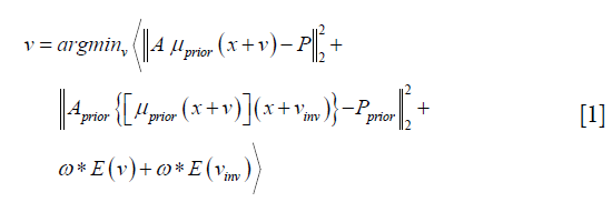
v denotes the forward DVF which deforms the CT/CBCTprior volume (uprior) to estimate the new CBCT. It will also deform the prior liver tumor contours onto the new CBCT for automatic liver tumor localization. vinv, on the other hand, denotes the inverse DVF which deforms the new CBCT back to the CT/CBCT prior volume. We also need to solve this inverse DVF, since the liver boundary DVF extracted from vinv will serve as the boundary condition for the biomechanical modeling step. vinv and v are inherently connected and could be solved jointly through multiple approaches (23,24). In this study we took a simple but effective approach by setting vinv = –v. A and Aprior denote the cone-beam projection ray-tracing matrices for the acquired cone-beam projections (P) and the simulated cone-beam projections (Pprior) of μprior, respectively. We defined A = Aprior since Pprior can be simulated at arbitrary angles. The deformation energy term (19), E(*), regularizes the DVF smoothness for stable and fast convergence. The weighting factors for the deformation energy term, ω, was empirically set to 0.025 (11). The gradient of the objective function defined in Eq. [1] can be explicitly computed to feed into convenient optimization routines such as the conjugate-gradient optimization scheme (13,19), which was employed in this study.
The 2D-3D deformation technique is built purely on projection intensity matching for DVF optimization. For regions with limited intensity variations such as intra-liver regions or caudal liver boundaries, the DVFs may not be accurately solved. In addition, the number of unknown DVF variables is three times the number of the CBCT image voxels. Such a great amount of unknowns leads to an ill-posed optimization problem that can be easily trapped at local optima, and necessitates further dimension reduction and regularization.
Motion modeling
To improve the DVF accuracy at low-contrast caudal liver boundaries, and to reduce the number of unknowns in the DVF optimization, we introduced motion modeling into the MM-Bio-CBCT estimation scheme. Compared with the traditional 2D-3D deformation technique, motion modeling views the DVF as a linear combination of several extracted motion modes (19,20,25). Instead of solving the whole DVF voxel-by-voxel, it solves the linear coefficients of several known motion modes to achieve substantial dimension reduction. In this study, we used a similar PCA based motion modeling strategy as that employed in (19,20). The general workflow of the motion modeling step has been depicted in Figure 3. In detail, for each liver patient, MM-Bio-CBCT learns a liver boundary motion model from his/her own prior 4D-CT/4D-CBCT imaging set. In radiation oncology, 4D-CT is frequently acquired for liver patients during treatment simulation to study the liver and liver tumor motion to customize motion management strategies. On each phase image of a selected 4D-CT/4D-CBCT, we manually contoured the whole liver volume and density-overrode the liver to a high Hounsfield Unit number to enhance the contrast of its boundary against surrounding normal tissues/organs, especially for the caudal boundary, to allow boundary-focused motion modeling. Using one phase as the reference phase (usually the end-inspiration or the end-expiration phase due to their relative stability and limited motion artifacts), we deformed the reference phase image to all the other phase images to reveal the motion patterns of the liver volume, via the Demons deformable registration algorithm (26). Note that since the motion model is built on the reference phase, all the following 2D-3D deformation and biomechanical modeling steps should also use the same reference phase volume as the prior image for the deformation-driven CBCT estimation.

The resulting inter-phase DVFs obtained from the deformable registration are subsequently processed through the PCA (25) to train a motion model that represents the key liver motion modes, especially at the caudal liver boundary. The motion model can be mathematically expressed as:

Same as Eq. [1], v denotes the forward DVF that deforms the prior image to the new CBCT image. The motion model, however, decouples v into several sub-components, including  . By principal component analysis, v0 ave is the mean DVF of all inter-phase DVFs. denotes the extracted principal components ranked by their relative importance. N denotes the total number of principal components used to construct the motion model. Same as the previous studies (19,20), we used N=3 as 3 principal components prove sufficient to capture the motion patterns, and using more components could adversely affect the modeling accuracy by introducing more noises and local DVF errors. Correspondingly, wj (j=1, 2, 3) are the weightings for each principal motion mode . Replacing the term v in Eq. [1] by Eq. [2] reduces the number of unknowns to 3*3 (Note that wj is a vector denoting three canonical directions, x, y and z) and allows fast DVF optimization using the same conjugate-gradient algorithm as the 2D-3D deformation.
In the above motion modeling framework, the liver boundary motion is successfully captured by manual liver contouring, density-overriding, and deformable registration. An implicit correlation has been established between the cranial and caudal liver boundary motion for each patient in the extracted motion modes. When MM-Bio-CBCT applies the learnt patient-specific motion model to estimate a DVF using Eq. [2], the implicit correlation between cranial and caudal liver boundary motion will generate more accurate DVFs at the caudal liver boundary, even if the deformation is mainly driven by the high contrast region in the cranial liver boundary.
However, the motion modeling step is only a coarse estimation of the overall liver volume motion with poor intra-liver DVF accuracy. Based on the motion modeling-derived DVF, further 2D-3D deformation and biomechanical modeling are needed to fine-tune the overall DVF especially for that within the liver.
Finite element analysis-based biomechanical modeling
There are multiple models for soft tissue biomechanical modeling and currently no ‘gold-standard’ exists (14,27,28). To model the liver, we used the Mooney-Rivlin material model, a hyper-elastic biomechanical model often applied towards modeling biological soft tissues (14,29). The deformation of the Mooney-Rivlin material is governed by the strain energy density function:
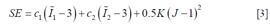
In Eq. [3], the first two terms quantify the change of the Mooney-Rivlin material’s shape towards stress. The third term quantifies the change of the material’s volume towards stress.  ,
,  and J are DVF derivatives, and c1, c2 and K denote the corresponding material parameters for them. We use c1 = c1 = 0.135 kPa and K = 27 kPa as the material parameters, which were empirically determined from a previous study (11).
As shown in Figure 4, the biomechanical modeling of liver involves a three-step process: (I) liver model generation from the prior image at the reference phase; (II) boundary condition and material property assignment; and (III) finite-element-analysis for intra-liver DVF optimization. For (I), we extracted the 3D liver contour, generated a corresponding liver surface mesh and subsequently modeled the whole liver volume as small, connected tetrahedral elements. For (II), we used the DVF solved from the motion modeling step as an initial start (Eq. [2]), fine-tuned it by 2D-3D deformation (Eq. [1]), and extracted the liver boundary DVF as the boundary condition. For (III), we solved the intra-liver DVF as a finite element problem using the open-source finite-element-analysis package FEBio (17).

In summary, MM-Bio-CBCT uses motion modeling to derive a coarse DVF with enhanced accuracy at the caudal liver boundary, and fine-tunes the DVF with an alternating scheme between 2D-3D deformation and biomechanical modeling (Figure 1). We found a total of 10 iterations are sufficient for the alternating scheme to achieve convergence, and used it as the convergence criteria.
Evaluation
We used both the digital XCAT phantom and real liver patient images to evaluate the MM-Bio-CBCT technique, and to compare its accuracy with that of the traditional 2D-3D deformation technique, the 2D-3D deformation technique with motion modeling, and the Bio-CBCT technique.
Using the XCAT phantom, we simulated a liver patient 4D-CT set as the prior information, and inserted a 3 cm-diameter spherical liver tumor that moves along with the liver volume. The motion of the XCAT phantom follows a diaphragm curve of 2 cm peak-to-peak amplitude, which controls the superior-inferior motion of all organs and tissues. It also follows a chest wall curve of 1.2 cm peak-to-peak amplitude, which controls the phantom’s anterior-posterior motion. We used the 10% phase of the 4D-CT as the reference phase (Figure 1) for motion modeling as well as for the deformation-driven CBCT estimation. To evaluate the robustness of the MM-Bio-CBCT technique towards motion variations between prior and new image acquisitions, we simulated different motion scenarios of the to-be-solved new CBCT images. In detail, three different amplitudes were used for the diaphragm motion curve (1, 2 and 3 cm) as well as for the chest wall motion curve (0.6, 1.2 and 1.8 cm) to simulate new ‘gold-standard’ 4D-CBCTs of different motion scenarios. From these simulated ‘gold-standard’ new 4D-CBCTs, we generated 20 phase-specific cone-beam projections at different respiration phases (20%, 50%, 70%, 90%), using the Siddon’s ray-tracing technique (30). The cone-beam projections covered a full 360° scan angle, and contained 512×384 pixels per projection, with each pixel spanning 0.776 mm × 0.776 mm in dimension. With the prior CT image at the reference phase (10%), the derived motion model from the prior 4D-CT set, and the simulated cone-beam projections, we applied the MM-Bio-CBCT technique to estimate CBCT images at different phases of different motion scenarios, and compared the resulting image quality and accuracy with those of other techniques. To evaluate the accuracy of using the solved DVFs for automatic liver tumor localization, we contoured the ‘gold-standard’ liver tumors from the simulated ‘gold-standard’ CBCT images via intensity thresholding, and calculated the DICE coefficient and the COME metrics between these ‘gold-standard’ contours and DVF-propagated liver tumor contours.
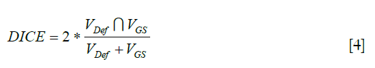
The Vdef symbol denotes the deformed liver tumor contour propagated by the solved DVFs and the VGS symbol denotes the liver tumor contoured on the ‘gold-standard’ image. A larger DICE coefficient indicates better match and higher tumor localization accuracy, with the optimal value being 1.
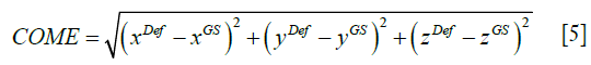
As shown in Eq. [5], COME calculates the Euclidean distance between the center-of-mass of the propagated liver tumor and that of the ‘gold-standard’ liver tumor, an important metric gauging the accuracy of using the automatically-localized tumor contour for radiotherapy treatment guidance.
In addition to the XCAT study, we performed additional simulation studies using real liver patient 4D-CT images. Three liver patient images were obtained from the open-access ITK medical image open library (http://midas.kitware.com/community/view/47). All of the 4D-CTs were contrast-enhanced, such that the liver tumors can be manually contoured as the ‘gold-standard’ to evaluate DVF-propagated liver tumor contours. For the real liver patient images, we applied the ‘leave-one-out’ strategy by dividing the 10-phase 4D-CT of each patient into two groups: one of nine phases (10–40%, 60–100%) as a subset for motion modeling, and the remaining one phase (50%) was used as the new ‘gold-standard’ CBCT image for evaluation. Similar to the XCAT study, we used the 10% phase image from the sub-4D-CT-set as the reference phase for motion modeling and deformation-driven CBCT estimation. For the patient study, different numbers of limited-view projections were simulated [5,10,20] to evaluate the potential of MM-Bio-CBCT in imaging dose reduction.
Results
Liver boundary deformation accuracy evaluation
Figure 5 compares the liver boundary deformation accuracy between Bio-CBCT and MM-Bio-CBCT techniques. The cranial liver boundaries, as marked by the upper dashed line, matched well between Bio-CBCT, MM-Bio-CBCT and ‘gold-standard’ CBCT images. The finding demonstrates that with high-contrast intensity information at the cranial liver boundary, the boundary DVF can be accurately solved by intensity-driven techniques. However, tracing down inferiorly, it becomes evident that the lower liver boundary is not well deformed by Bio-CBCT, as pointed out by the markers and indicated by the dashed lines. The results show that the limited contrast at the caudal liver side failed to deform the liver boundary accurately by intensity-based techniques. Using motion modeling, MM-Bio-CBCT improves the deformation accuracy at the caudal liver side, as shown in Figure 5, which helps to further improve the accuracy of biomechanical modeling in solving intra-liver DVFs.

CBCT image comparison
Figure 6 compares the reconstructed/estimated CBCT images and the ‘gold-standard’ CBCT images. The zoomed-in display focuses on the tumor area to compare the accuracy of DVF-propagated liver tumors. It is evident that using only 20 cone-beam projections, the CBCT images reconstructed by the clinical Feldkamp-Davis-Kress (FDK) algorithm (31) contain excessive artifacts and the tumor information has been smeared out. The deformation-driven techniques, on the other hand, preserve the high-quality HU information from the prior image with no streak artifacts. Nonetheless, based on pure projection intensity matching, the 2D-3D deformation technique fails to deform the intra-liver tumor to its correction location. The 2D-3D deformation technique with motion modeling also fails to correctly localize the low-contrast liver tumor. Using biomechanical modeling to boost DVF at low-contrast regions, the Bio-CBCT technique generates better matched liver tumors to ‘gold-standard’, however not as accurate as the MM-Bio-CBCT technique. MM-Bio-CBCT technique deforms the low-contrast liver tumor to well match with the ‘gold-standard’, by combining motion modeling with biomechanical modeling.

Figure 7 shows multi-phase images solved by MM-Bio-CBCT for the XCAT study, with corresponding ‘gold-standard’ multi-phase CBCT images shown as reference. The solved tumor motion trajectory by MM-Bio-CBCT matches well with that in the reference images.

Quantitative evaluation results
Figure 8 presents the quantitative evaluation results for the XCAT study. Each boxplot contains 12 data points, featuring the three simulated motion scenarios, and the four CBCT phases (20%, 50%, 70%, 90%). The average (± SD) DICE coefficients for 0 DVF (no deformation), 2D-3D deformation, 2D-3D deformation with motion modeling, Bio-CBCT and MM-Bio-CBCT techniques were 0.49 (±0.33), 0.57 (±0.31), 0.78 (±0.26), 0.83 (±0.21) and 0.89 (±0.11), respectively. The corresponding average (± SD) COMEs were 12.7 mm (±10.4 mm), 9.5 mm (±8.0 mm), 4.5 mm (±5.8 mm), 3.5 mm (±4.7 mm) and 2.2 mm (±2.1 mm), respectively. In Figure 8, two outliers exist for the MM-Bio-CBCT results, one for phase 50% (DICE: 0.61, COME: 7.9 mm) and the other for phase 70% (DICE: 0.77, COME: 4.6 mm). Both cases are from the motion scenario of relatively large diaphragm curve amplitude (3 cm) and chest wall curve amplitude (1.8 cm). These two cases are particularly challenging, since the liver tumor volume in the prior image is far apart the liver tumor volumes in the ‘gold-standard’ new CBCT images after the large increase of motion amplitudes, with center-of-mass distance reaching ~3 cm and with minimum volume overlap (DICE ~0).

As shown in Table 1, MM-Bio-CBCT provides consistently more accurate DVFs to propagate the prior liver tumor contours to match the best with the ‘gold-standard’. Increasing the number of projections generally improves the accuracy of automatic liver tumor localization, especially for the 2D-3D deformation technique and the Bio-CBCT technique. For 2D-3D deformation with motion modeling, and for MM-Bio-CBCT, the improvements are not substantial. It is caused by the use of motion modeling, which achieves substantial parameter dimension reduction to allow DVF optimization by using only a few projections. Thus, increasing the number of projections will not substantially improve their results. For 2D-3D deformation with motion modeling, even though the motion modeling step establishes a good estimate of the DVF, the technique fails to further improve the DVF accuracy at intra-liver regions as the MM-Bio-CBCT technique does.

Full table
Discussion
Liver tumor localization has been a challenging task for radiotherapy, even after the substantial developments and improvements of X-ray-based imaging guidance techniques in past decades. The radiotherapy treatments usually have to rely on surrogates to localize the liver tumor, either a high-contrast anatomical structure close to tumor (for instance, diaphragm, or a liver cyst), or several implanted high contrast fiducial markers (6). However, these surrogates suffer from either the lack of motion correlation with the liver tumor, or from invasiveness and potential surrogate migrations, or both. In this study, we took a different approach to localize the liver tumor. Instead of directly locating the tumors on the X-ray image via visual clues, we developed a new CBCT estimation technique to solve DVFs to morph a prior high quality CT/CBCT image to the new CBCT image, which naturally transfers the liver tumor contours from the prior image to the new image for automatic liver tumor localization. The developed MM-Bio-CBCT technique combines 2D-3D deformation, principal-component-analysis based motion modeling, and finite-element-analysis based biomechanical modeling to solve DVFs of high accuracy for tumor localization. The use of motion modeling not only achieves substantial parameter dimension reduction for fast optimization, but more importantly solves accurate DVFs at the caudal liver boundary where the image contrast could be insufficient to drive accurate DVF optimization (Figure 5). The accurate liver boundary DVF, input as the boundary condition for finite-element-analysis based biomechanical modeling, further improves the intra-liver DVF to accurately localize the liver tumor. Both the motion modeling and the biomechanical modeling steps are needed to achieve the best liver tumor localization accuracy, as evidenced in the study results comparing different techniques (Figure 6, Figure 8, Table 1). Using as few as 5 projections, the MM-Bio-CBCT technique can achieve an average tumor localization accuracy of ~2 mm, which allows substantial margin reduction to reduce the toxicity of current liver radiotherapy. It also opens up an avenue for further dose escalation to explore the full potential of advanced treatment techniques like liver SBRT. Though developed for liver, the MM-Bio-CBCT technique can also be applied towards other sites where accurate tumor localization might be challenging, such as the kidney.
By altering the amplitudes of the motion curves, the XCAT study evaluates the robustness of different techniques towards motion variations. The MM-Bio-CBCT technique remains the most accurate technique, with the lowest localization errors among all. However, when the motion variation causes significant deformations of the new CBCT compared to the prior image, the localization error of MM-Bio-CBCT also increases considerably. It could be caused by the limitation of motion modeling, which works on a prior 4D imaging set and may fail to predict new motion patterns much different from the prior motion patterns. To solve this problem, we could use patient breathing coaching or abdominal compression, to regularize the patient breathing motion to achieve shallower, more reproducible liver motion such that the motion model will remain valid throughout the treatment course. A more robust motion modeling technique that is able to account for large motion variations will also be investigated in future. Another interesting finding, as shown in Table 1, is that the accuracy of MM-Bio-CBCT is less dependent of the number of projections used in CBCT estimation. The use of motion modeling allows us to use a limited number of projections for DVF optimization, since there are only 9 unknowns to be solved in the motion model (Eq. [2]). If the motion pattern is similar between different image acquisitions, we can use an extremely limited number of projections, potentially just one single projection (32), to achieve real-time liver tumor localization for treatment monitoring and tumor tracking.
The motion modeling steps of MM-Bio-CBCT, including the liver density overriding, the Demons registration and the principal component analysis, are streamlined and fully automatic. The other steps including 2D-3D deformation, biomechanical modeling and finite element analysis are also fully automatic. The liver segmentation step of this study is manually performed on 4D-CT sets. It is an off-line process that can be done any time after the 4D-CT acquisition and does not take patient on-line treatment time. In addition, there are many studies on automatic liver segmentation with very encouraging results (33-36). By introducing automatic liver segmentation into our algorithm, MM-Bio-CBCT can be made fully automatic to remove the needs of human input and satisfy the clinical needs of convenience and efficiency. Currently, for MM-Bio-CBCT we used a semi-graphic processing unit (GPU)-accelerated scheme, which takes ~20 minutes when using 5 projections for estimation. Further acceleration is warranted in future studies to render the algorithm more clinically applicable.
In this study, we simulated the cone-beam projections from the XCAT phantom images and real patient images using the ray-tracing technique, an approach widely applied in previous studies (12,13,19). Using simulated images for evaluation allows us to have the ‘gold-standard’ for quantitative evaluation. In future studies, a more realistic simulation scheme like the Monte-Carlo approach should be used instead to further evaluate the robustness of the MM-Bio-CBCT technique in the presence of degrading signals including scatter, noise and other imaging artifacts (11,37). There are multiple previous studies investigating different techniques to reduce these signals (38,39), and one of our recent developments by using convolutional neural networks also demonstrated encouraging results in removing these degrading signals (40). Real clinical projections are also warranted to be evaluated, provided that adequate ‘gold-standard’ can be obtained for evaluation. For instance, we can use implanted radiopaque fiducial markers near the tumor as the ‘gold-standard’ to cross-evaluate the MM-Bio-CBCT technique, provided that the markers are sufficient in number to reduce the effects of marker migration, and they are fairly close to the tumor to demonstrate actual tumor motion.
In this study, we used prior 4D-CT sets to provide the information to establish motion models. However, sometimes the 4D-CT or 4D-CBCT image quality can be low with artifacts in the abdominal region that may negatively impact clinical applications. The motion modeling algorithm employed in this study is to some extent robust to the image quality issues, since the motion model is derived from density-overridden 4D liver volumes. By density-overriding, intra-liver artifacts can be removed. In addition, the motion model is intended to capture the liver boundary motion and the inherent motion correlation, thus artifacts exterior to the liver boundary may not pose significant issues either. Nonetheless, cautions should still be taken when selecting the reference phase image from 4D-CT/4D-CBCT for motion modeling and deformation-driven CBCT estimation, since imaging artifacts may be passed along from this prior image onto the estimated CBCT images. Thus, it is recommended to select the end-inspiration or the end-expiration phase as the reference phase due to their relative stability and limited motion artifacts. For scenarios where the patient breathing is very irregular that substantially degrades the image quality of even the end-inspiration and end-expiration phases, we could use coaching or audio-visual feedback systems to regularize patient breathing (41).
In radiotherapy, 4D-CT is often acquired for liver patients to assess their motion to customize the motion management techniques. For some patients, for instance those receiving breath-hold radiotherapy treatments, a prior 4D-CT/ 4D-CBCT may not be available for motion modeling. Future studies are warranted to develop techniques to tailor to these patients, where an atlas-based approach or a generalized motion model might be used instead to improve the DVF accuracy at the caudal liver boundary.
Acknowledgments
The authors would like to thank Dr. Paul Segars from the Duke University Medical Center for sharing the XCAT phantom for the simulation study.
Funding: This work was supported in part by grants from the US National Institutes of Health (R01 EB020366, R01 EB027898 and R01 CA184173), and from the Cancer Prevention and Research Institute of Texas (RP160661).
Footnote
Conflicts of Interest: The authors have no conflicts of interest to declare.
References
- Siegel RL, Miller KD, Jemal A. Cancer statistics, 2016. CA Cancer J Clin 2016;66:7-30. [Crossref] [PubMed]
- Disibio G, French SW. Metastatic patterns of cancers: results from a large autopsy study. Arch Pathol Lab Med 2008;132:931-9. [PubMed]
- Keane FK, Hong TS. Role and Future Directions of External Beam Radiotherapy for Primary Liver Cancer. Cancer Control 2017;24:1073274817729242. [Crossref] [PubMed]
- Liu E, Stenmark MH, Schipper MJ, Balter JM, Kessler ML, Caoili EM, Lee OE, Ben-Josef E, Lawrence TS, Feng M. Stereotactic body radiation therapy for primary and metastatic liver tumors. Transl Oncol 2013;6:442-6. [Crossref] [PubMed]
- Pan CC, Kavanagh BD, Dawson LA, Li XA, Das SK, Miften M, Ten Haken RK. Radiation-associated liver injury. Int J Radiat Oncol Biol Phys 2010;76:S94-100. [Crossref] [PubMed]
- Park JC, Park SH, Kim JH, Yoon SM, Song SY, Liu Z, Song B, Kauweloa K, Webster MJ, Sandhu A, Mell LK, Jiang SB, Mundt AJ, Song WY. Liver motion during cone beam computed tomography guided stereotactic body radiation therapy. Med Phys 2012;39:6431-42. [Crossref] [PubMed]
- Rohlfing T, Maurer CR Jr, O'Dell WG, Zhong J. Modeling liver motion and deformation during the respiratory cycle using intensity-based nonrigid registration of gated MR images. Med Phys 2004;31:427-32. [Crossref] [PubMed]
- Chan MK, Lee V, Chiang CL, Lee FA, Law G, Sin NY, Siu KL, Wong FC, Tung SY, Luk H, Blanck O. Lipiodol versus diaphragm in 4D-CBCT-guided stereotactic radiotherapy of hepatocellular carcinomas. Strahlenther Onkol 2016;192:92-101. [Crossref] [PubMed]
- Jaffray DA, Siewerdsen JH. Cone-beam computed tomography with a flat-panel imager: initial performance characterization. Med Phys 2000;27:1311-23. [Crossref] [PubMed]
- Zhang Y, Tehrani JN, Wang J. A Biomechanical Modeling Guided CBCT Estimation Technique. IEEE Trans Med Imaging 2017;36:641-52. [Crossref] [PubMed]
- Zhang Y, Folkert MR, Li B, Huang X, Meyer JJ, Chiu T, Lee P, Tehrani JN, Cai J, Parsons D, Jia X, Wang J. 4D liver tumor localization using cone-beam projections and a biomechanical model. Radiother Oncol 2019;133:183-92. [Crossref] [PubMed]
- Ren L, Chetty IJ, Zhang J, Jin JY, Wu QJ, Yan H, Brizel DM, Lee WR, Movsas B, Yin FF. Development and clinical evaluation of a three-dimensional cone-beam computed tomography estimation method using a deformation field map. Int J Radiat Oncol Biol Phys 2012;82:1584-93. [Crossref] [PubMed]
- Wang J, Gu X. High-quality four-dimensional cone-beam CT by deforming prior images. Phys Med Biol 2013;58:231-46. [Crossref] [PubMed]
- Tehrani JN, Yang Y, Werner R, Lu W, Low D, Guo X, Wang J. Sensitivity of tumor motion simulation accuracy to lung biomechanical modeling approaches and parameters. Phys Med Biol 2015;60:8833-49. [Crossref] [PubMed]
- Werner R, Ehrhardt J, Schmidt R, Handels H. Patient-specific finite element modeling of respiratory lung motion using 4D CT image data. Med Phys 2009;36:1500-11. [Crossref] [PubMed]
- Al-Mayah A, Moseley J, Velec M, Hunter S, Brock K. Deformable image registration of heterogeneous human lung incorporating the bronchial tree. Med Phys 2010;37:4560-71. [Crossref] [PubMed]
- Maas SA, Ellis BJ, Ateshian GA, Weiss JA. FEBio: finite elements for biomechanics. J Biomech Eng 2012;134:011005. [Crossref] [PubMed]
- Velec M, Moseley JL, Eccles CL, Craig T, Sharpe MB, Dawson LA, Brock KK. Effect of breathing motion on radiotherapy dose accumulation in the abdomen using deformable registration. Int J Radiat Oncol Biol Phys 2011;80:265-72. [Crossref] [PubMed]
- Zhang Y, Yin FF, Segars WP, Ren L. A technique for estimating 4D-CBCT using prior knowledge and limited-angle projections. Med Phys 2013;40:121701. [Crossref] [PubMed]
- Zhang Y, Yin FF, Pan T, Vergalasova I, Ren L. Preliminary clinical evaluation of a 4D-CBCT estimation technique using prior information and limited-angle projections. Radiother Oncol 2015;115:22-9. [Crossref] [PubMed]
- Thor M, Petersen JB, Bentzen L, Hoyer M, Muren LP. Deformable image registration for contour propagation from CT to cone-beam CT scans in radiotherapy of prostate cancer. Acta Oncol 2011;50:918-25. [Crossref] [PubMed]
- Harris W, Yin F, Wang C, Zhang Z, Chang Z, Cai J, Zhang Y, Ren L. Ultrafast Volumetric Cine Magnetic Resonance Imaging (UVC-MRI) for Real-Time 3-Dimensional Target Localization/Tracking. Int J Radiat Oncol Biol Phys 2016;96:E626. [Crossref]
- Chen M, Lu W, Chen Q, Ruchala KJ, Olivera GH. A simple fixed-point approach to invert a deformation field. Med Phys 2008;35:81-8. [Crossref] [PubMed]
- Wang J, Gu X. Simultaneous motion estimation and image reconstruction (SMEIR) for 4D cone-beam CT. Med Phys 2013;40:101912. [Crossref] [PubMed]
- Li R, Lewis JH, Jia X, Zhao T, Liu W, Wuenschel S, Lamb J, Yang D, Low DA, Jiang SB. On a PCA-based lung motion model. Phys Med Biol 2011;56:6009-30. [Crossref] [PubMed]
- Gu X, Pan H, Liang Y, Castillo R, Yang D, Choi D, Castillo E, Majumdar A, Guerrero T, Jiang SB. Implementation and evaluation of various demons deformable image registration algorithms on a GPU. Phys Med Biol 2010;55:207-19. [Crossref] [PubMed]
- Al-Mayah A, Moseley J, Hunter S, Velec M, Chau L, Breen S, Brock K. Biomechanical-based image registration for head and neck radiation treatment. Phys Med Biol 2010;55:6491-500. [Crossref] [PubMed]
- Kao PH, Lammers SR, Tian L, Hunter K, Stenmark KR, Shandas R, Qi HJ. A microstructurally driven model for pulmonary artery tissue. J Biomech Eng 2011;133:051002. [Crossref] [PubMed]
- Nasehi Tehrani J, Wang J. Mooney-Rivlin biomechanical modeling of lung with Inhomogeneous material. Conf Proc IEEE Eng Med Biol Soc 2015;2015:7897-900. [PubMed]
- Siddon RL. Fast calculation of the exact radiological path for a three-dimensional CT array. Med Phys 1985;12:252-5. [Crossref] [PubMed]
- Feldkamp LA, Davis LC, Kress JW. Practical Cone-Beam Algorithm. J Opt Soc Am A Opt Image Sci Vis 1984;1:612-9. [Crossref]
- Li R, Jia X, Lewis JH, Gu X, Folkerts M, Men C, Jiang SB. Single-projection based volumetric image reconstruction and 3D tumor localization in real time for lung cancer radiotherapy. Med Image Comput Comput Assist Interv 2010;13:449-56.
- Lu X, Xie Q, Zha Y, Wang D. Fully automatic liver segmentation combining multi-dimensional graph cut with shape information in 3D CT images. Sci Rep 2018;8:10700. [Crossref] [PubMed]
- Hu P, Wu F, Peng J, Liang P, Kong D. Automatic 3D liver segmentation based on deep learning and globally optimized surface evolution. Phys Med Biol 2016;61:8676-98. [Crossref] [PubMed]
- Zheng Z, Zhang X, Xu H, Liang W, Zheng S, Shi Y. A Unified Level Set Framework Combining Hybrid Algorithms for Liver and Liver Tumor Segmentation in CT Images. Biomed Res Int 2018;2018:3815346. [Crossref] [PubMed]
- Li X, Chen H, Qi X, Dou Q, Fu CW, Heng PA. H-DenseUNet: Hybrid Densely Connected UNet for Liver and Tumor Segmentation From CT Volumes. IEEE Trans Med Imaging 2018;37:2663-74. [Crossref] [PubMed]
- Jia X, Yan H, Cervino L, Folkerts M, Jiang SB. A GPU tool for efficient, accurate, and realistic simulation of cone beam CT projections. Med Phys 2012;39:7368-78. [Crossref] [PubMed]
- Ren L, Chen Y, Zhang Y, Giles W, Jin J, Yin FF. Scatter Reduction and Correction for Dual-Source Cone-Beam CT Using Prepatient Grids. Technol Cancer Res Treat 2016;15:416-27. [PubMed]
- Wang J, Mao W, Solberg T. Scatter correction for cone-beam computed tomography using moving blocker strips: a preliminary study. Med Phys 2010;37:5792-800. [Crossref] [PubMed]
- Zhang Y, Chen L, Li B, Folkert M, Jia X, Gu X, Wang J. Incorporating biomechanical modeling and deep learning into a deformation-driven liver CBCT reconstruction technique. Med Imaging 2019. doi.org/ [Crossref]
- George R, Chung TD, Vedam SS, Ramakrishnan V, Mohan R, Weiss E, Keall PJ. Audio-visual biofeedback for respiratory-gated radiotherapy: impact of audio instruction and audio-visual biofeedback on respiratory-gated radiotherapy. Int J Radiat Oncol Biol Phys 2006;65:924-33. [Crossref] [PubMed]

