|
Cite this article as: Pang Y, Zhang X. Precompensation for mutual coupling
between array elements in parallel excitation. Quant Imaging Med Surg
2011;1:4-10. DOI: 10.3978/j.issn.2223-4292.2011.11.02
Original Article
Precompensation for mutual coupling between array elements in
parallel excitation
Yong Pang1, Xiaoliang Zhang1,2
1Department of Radiology and Biomedical Imaging, University of California San Francisco, San Francisco, CA, United States; 2UCSF/UC Berkeley Joint Graduate Group in Bioengineering, San Francisco & Berkeley, CA, United States
Corresponding to: Xiaoliang Zhang, PhD. Dept. of Radiology and Biomedical Imaging,
University of California San Francisco, Byers Hall, Room 102, 1700 4th ST, San
Francisco, CA94158-2330, USA. Tel: 1-415-514-4801. Email: xiaoliang.zhang@ucsf.edu.
|
|
Introduction
Multidimensional spatially selective RF pulses have been used in MRI
to limit the electromagnetic signal emitted from the imaging object
within arbitrarily shaped and spatially restricted areas ( 1-6). This
approach requires homogeneous radiofrequency (RF) field to ensure
the accuracy of the excitation profile, especially for spin echo imaging.
This requirement has impeded the further development and application
of multidimensional spatial RF pulses to ultrahigh field MRI (7 Tesla
and beyond) ( 7-13) in which homogeneous RF field is difficult to
be achieved ( 8, 14-18) due to the high frequency wave effect in the
conductive and high dielectric imaging object such as human body ( 19).
To achieve homogeneous RF field distribution and shorten the pulse
width, parallel transmission ( 20-28) is suggested to perform spatial
selective excitation using a coil array and the sensitivity information
of each element. The amplitude and phase of each element are
independently controlled to manipulate the RF field distribution within
imaging object to ultimately achieve B1 homogeneity ( 29, 30). The
parallel transmission can be used not only in small-tip-angle excitation,
but also in large-tip-angle excitation and refocusing pulses at ultrahigh
fields ( 31-33). Although the average and local specific absorption ratio
(SAR) increase with the acceleration factor in parallel transmission ( 34),
the SAR can be optimized using different strategies such as variable
sampling rate or optimized k-space trajectories ( 21, 35-38), providing
feasible ways to make tradeoffs between the acceleration factor and the
power deposition. The mutual coupling has been a critical problem in RF coil array
design ( 39, 40), especially at ultrahigh fields where the imaging sample
mediates the mutual coupling among the array elements ( 9, 11, 12, 29, 41-43). Comparing with the situation in parallel reception, this decoupling
problem becomes more critical in parallel transmission, deteriorating
the excitation accuracy and degrading the image quality. Although a
variety of decoupling schemes have been developed to address the issue
( 12, 14, 29, 40, 42-46), insufficient decoupling among array elements is
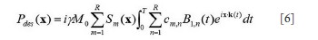
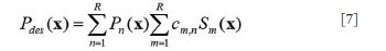
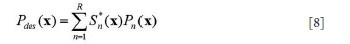
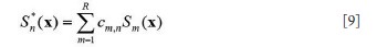
still a major problem hindering the development and application of parallel transmission. In this work, a precompensation method is proposed to address the
mutual coupling effect in transmit SENSE by introducing the mutual
coupling coefficient matrix into the RF pulses design procedure of the
transmit SENSE. Studies show that by using this precompensation
technique, the mutual coupling effect on the excitation pattern can be
compensated by using the corrected RF pulses as long as the mutual
coupling between array elements is not high enough to cause a clear
split of the element resonance peak, or in a weakly coupling case.
This precompensation technique provides a valuable approach to
performance optimization of transmit SENSE or parallel excitation
using multichannel RF transmit arrays with non-negligible mutual
coupling between array elements.
|
|
References
- Pauly JM, Nishimura DG, Macovski A. Introduction to: A k-space analysis
of small-tip-angle excitation. J Magn Reson 2011. [Epub ahead of print].
- Pauly JM, Nishimura D, Macovski A. A linear class of large-tip-angle
selective excitation pulses. J Magn Reson 1989;82:571-87.
- Hardy CJ, Cline HE. Spatial localization in 2 dimensions using NMR
designer pulses. J Magn Reson 1989;82:647-54.
- Hardy CJ, Cline HE. Broadband nuclear magnetic resonance pulses with
two-dimensional spatial selectivity. J Appl Phys 1989;66:1513-6.[LinkOut]
- Yuan J, Zhao TC, Tang Y, et al. Reduced field-of-view single-shot fast spin
echo imaging using two-dimensional spatially selective radiofrequency
pulses. J Magn Reson Imaging 2010;32:242-8.[LinkOut]
- Yuan J, Madore B, Panych LP. Spatially varying fat-water excitation using
short 2DRF pulses. Magn Reson Med 2010;63:1092-7.[LinkOut]
- Lei H, Zhu XH, Zhang XL, et al. In vivo 31P magnetic resonance
spectroscopy of human brain at 7 T: an initial experience. Magn Reson
Med 2003;49:199-205.[LinkOut]
- Vaughan JT, Garwood M, Collins CM, et al. 7T vs. 4T: RF power,
homogeneity, and signal-to-noise comparison in head images. Magn Reson
Med 2001;46:24-30.[LinkOut]
- Wiggins GC, Potthast A, Triantafyllou C, et al. Eight-channel phased array
coil and detunable TEM volume coil for 7 T brain imaging. Magn Reson
Med 2005;54:235-40.[LinkOut]
- Yacoub E, Van De Moortele PF, Shmuel A, et al. Signal and noise
characteristics of Hahn SE and GE BOLD fMRI at 7 T in humans.
Neuroimage 2005;24:738-50.[LinkOut]
- Wu B, Wang C, Krug R, et al. 7T human spine imaging arrays with
adjustable inductive decoupling. IEEE Trans Biomed Eng 2010;57:397-
403.[LinkOut]
- Li Y, Xie Z, Pang Y, et al. ICE decoupling technique for RF coil array
designs. Med Phys 2011;38:4086-93.[LinkOut]
- Pang Y, Zhang X, Xie Z, et al. Common-Mode Differential-Mode (CMDM)
Method for Double-Nuclear MR Signal Excitation and Reception at
Ultrahigh Fields. IEEE Trans Med Imaging 2011;30:1965-73.[LinkOut]
- Zhang X, Ugurbil K, Chen W. Microstrip RF surface coil design
for extremely high-field MRI and spectroscopy. Magn Reson Med
2001;46:443-50.[LinkOut]
- Zhang X, Ugurbil K, Sainati R, et al. An inverted-microstrip resonator
for human head proton MR imaging at 7 tesla. IEEE Trans Biomed Eng
2005;52:495-504.[LinkOut]
- Ibrahim TS, Lee R, Baertlein BA, et al. Effect of RF coil excitation on field
inhomogeneity at ultra high fields: a field optimized TEM resonator. Magn
Reson Imaging 2001;19:1339-47.[LinkOut]
- Collins CM, Yang QX, Wang JH, et al. Different excitation and reception
distributions with a single-loop transmit-receive surface coil near a headsized
spherical phantom at 300 MHz. Magn Reson Med 2002;47:1026-8.[LinkOut]
- Zhang X, Ugurbil K, Chen W. A microstrip transmission line volume coil
for human head MR imaging at 4T. J Magn Reson 2003;161:242-51.[LinkOut]
- Yang QX, Wang J, Zhang X, et al. Analysis of wave behavior in lossy
dielectric samples at high field. Magn Reson Med 2002;47:982-9.[LinkOut]
- Katscher U, Bornert P, Leussler C, et al. Transmit SENSE. Magn Reson
Med 2003;49:144-50.[LinkOut]
- Zhu Y. Parallel excitation with an array of transmit coils. Magn Reson Med
2004;51:775-84.[LinkOut]
- Grissom W, Yip CY, Zhang Z, et al. Spatial domain method for the design of
RF pulses in multicoil parallel excitation. Magn Reson Med 2006;56:620-9.[LinkOut]
- Katscher U, Bornert P. Parallel RF transmission in MRI. NMR Biomed
2006;19:393-400.[LinkOut]
- Katscher U, Börnert P, van den Brink JS. Theoretical and numerical aspects
of transmit SENSE. IEEE Trans Med Imaging 2004;23:520-5.[LinkOut]
- Lee D, Lustig M, Grissom WA, wt al. Time-optimal design for
multidimensional and parallel transmit variable-rate selective excitation.
Magn Reson Med 2009;61:1471-9.[LinkOut]
- Ma C, Xu D, King KF, et al. Joint design of spoke trajectories and RF pulses
for parallel excitation. Magn Reson Med 2010. [Epub ahead of print].
- Yip CY, Grissom WA, Fessler JA, et al. Joint design of trajectory and RF
pulses for parallel excitation. Magn Reson Med 2007;58:598-604.[LinkOut]
- Zhang Z, Yip CY, Grissom W, et al. Reduction of transmitter B1
inhomogeneity with transmit SENSE slice-select pulses. Magn Reson Med
2007;57:842-7.[LinkOut]
- Adriany G, Van de Moortele PF, Wiesinger F, et al. Transmit and receive
transmission line arrays for 7 Tesla parallel imaging. Magn Reson Med
2005;53:434-45.[LinkOut]
- Wu B, Wang C, Lu J, et al. Multi-Channel Microstrip Transceiver Arrays
Using Harmonics for High Field MR Imaging in Humans. IEEE Trans Med
Imaging 2011. [Epub ahead of print].
- Grissom WA, Yip CY, Wright SM, et al. Additive angle method for fast
large-tip-angle RF pulse design in parallel excitation. Magn Reson Med
2008;59:779-87.[LinkOut]
- Setsompop K, Alagappan V, Zelinski AC, et al. High-flip-angle sliceselective
parallel RF transmission with 8 channels at 7 T. J Magn Reson
2008;195:76-84.[LinkOut]
- Xu D, King KF, Zhu Y, et al. A noniterative method to design large-tip-angle
multidimensional spatially-selective radio frequency pulses for parallel
transmission. Magn Reson Med 2007;58:326-34.[LinkOut]
- Zelinski AC, Angelone LM, Goyal VK, et al. Specific absorption rate
studies of the parallel transmission of inner-volume excitations at 7T. J
Magn Reson Imaging 2008;28:1005-18.[LinkOut]
- Homann H, Graesslin I, Nehrke K, et al. Specific absorption rate reduction
in parallel transmission by k-space adaptive radiofrequency pulse design.
Magn Reson Med 2010. [Epub ahead of print].
- Liu Y, Feng K, McDougall MP, et al. Reducing SAR in parallel excitation
using variable-density spirals: a simulation-based study. Magn Reson
Imaging 2008;26:1122-32.[LinkOut]
- Liu Y, Ji JX. Minimal-SAR RF pulse optimization for parallel transmission
in MRI. Conf Proc IEEE Eng Med Biol Soc 2008;2008:5774-7.
- Wu X, Akgün C, Vaughan JT, et al. Adapted RF pulse design for SAR
reduction in parallel excitation with experimental verification at 9.4T. J
Magn Reson 2010. [Epub ahead of print].
- Roemer PB, Edelstein WA, Hayes CE, et al. The NMR phased array. Magn
Reson Med 1990;16:192-225.[LinkOut]
- Lee RF, Giaquinto RO, Hardy CJ. Coupling and decoupling theory and its
application to the MRI phased array. Magn Reson Med 2002;48:203-13.[LinkOut]
- Wu B, Wang C, Kelley DA, et al. Shielded microstrip array for 7T human
MR imaging. IEEE Trans Med Imaging 2010;29:179-84.[LinkOut]
- Gilbert KM, Curtis AT, Gati JS, et al. Transmit/receive radiofrequency coil
with individually shielded elements. Magn Reson Med 2010;64:1640-51.[LinkOut]
- Zhang X, Ugurbil K, Sainati R, et al. An inverted-microstrip resonator
for human head proton MR imaging at 7 tesla. IEEE Trans Biomed Eng
2005;52:495-504.[LinkOut]
- Setsompop K, Wald LL, Alagappan V, et al. Parallel RF transmission with
eight channels at 3 Tesla. Magn Reson Med 2006;56:1163-71.[LinkOut]
- Chu X, Yang X, Liu Y, et al. Ultra-low output impedance RF power
amplifier for parallel excitation. Magn Reson Med 2009;61:952-61.[LinkOut]
- Vossen M, Teeuwisse W, Reijnierse M, et al. A radiofrequency coil
configuration for imaging the human vertebral column at 7 T. J Magn
Reson 2011;208:291-7.[LinkOut]
|