
Analysis of geometric variation of neck node levels during image-guided radiotherapy for nasopharyngeal carcinoma: recommended planning margins
Introduction
Radiation therapy (RT) is the primary treatment modality for nasopharyngeal cancer (NPC) (1). Owing to tumor and nodal volume shrinkage and weight loss (2), the geometry of the tumor (3-6), lymph nodes (LNs) in the neck (4), and the organs at risk (OAR) such as the parotid glands (5,7) undergo substantial change during a typical 5–7-week-long treatment course. The adaptive modification according to anatomical changes is one of the possible solutions to minimize geometrical uncertainties (2,8).
More than 80% of NPC patients had involvement of neck LNs (9), and irradiation to the neck nodal levels (NNLs) is necessary to eradicate the macroscopic neck LNs and reduce the risk of recurrence in each NNL (10). Gregoire et al. (11-13) definitively defined the NNLs based-on computed tomography (CT), and each NNL can be clearly contoured in axial CT images. However, from the upper to lower neck, both the anatomical structures and the probability of metastatic disease are significantly different (9). During chemoradiotherapy, the geometrical changes of the whole neck might not be homogenous. With image-guided RT, the head and cranial neck could be well matched (14), yet the caudal neck and shoulder usually do not match very well due to the anatomical deformations (14) and generous set-up uncertainties (15-17). The NNL is covered from the cranial to caudal neck and the supraclavicular region. Moreover, the geometrical variations are substantial and require an individualized margin to maintain the geometrical and dose coverage throughout treatment. The aim of this study was to determine the volume, position, and shape variations of each NNL, for locally advanced NPC. Moreover, we aimed to estimate the individual margin of each NNL to maintain acceptable geometrical coverage during the course of chemo-radiotherapy, which will be useful for adaptive RT for head and neck cancer.
Methods
Imaging data and treatment
Twenty consecutive patients (15 men, 5 women) with locally advanced NPC were included in this cohort study, approved by the ethical committee of Hubei Cancer Hospital; all patients provided written informed consent. CT was performed as reported previously (4,18). Thirteen patients received concurrent chemoradiation and 7 with induction chemotherapy and concurrent chemoradiotherapy (4). Briefly, each patient underwent an enhanced planning CT (CTplan) scan and six weekly repeated CT (CTrep) scans (at the 5th, 10th, 15th, 20th, 25th, and 30th radiation fractions) without contrast during chemotherapy and intensity-modulated radiotherapy (IMRT) (4). After registering the images and defining the target volume and OARs, an inverse IMRT dynamic plan with the individualized prescribed dose was delivered to the primary tumor and positive neck LNs of the planning target volume (PTV) (4). In brief, the prescribed dose to primary tumor and positive neck LNs, the high-risk elective NNLs were 69.3–72.6 Gy and 59.4–62.7 Gy in 33 fractions and 50.4 Gy in 28 fractions to the low-risk NNLs (4). This study was designed only to document and calculate the geometrical changes of NNLs and the actual planning target delivered was not changed.
Imaging registration and delineation of NNLs
The software program (WRLDMATC) (4,19) was used for CT image registration and NNLs delineation. A rigid registration was performed based on bone match, in which the match box is large enough to cover the whole possible PTV (as is our routine practice between each CTrep and its CTplan). Then all NNLs were delineated at each transverse CT section by a single radiation oncologist (W Tan) devoted to head and neck cancer, according to the criteria by Gregoire et al. (11,12). The rigid registration criteria enabled all seven CT images to share the same coordinate system and could be used for NNLs delineation and geometrical change analyses.
Metrics of geometric changes
The geometric changes of NNLs were estimated by volume loss, positional displacement, and shape deformation. The same NNL in the CTplan and the CTrep, the volume in the CTplan (plan) and CTrep (repeat) and the overlapping volume (plan∩repeat) were automatically calculated. For each NNL, all the parameters in the CTplan were set as the baseline and those in the CTrep were used to quantify the geometrical changes.
The spatial displacement of the center of mass (COM), calculated automatically by the research software, was used to estimate the NNL displacement during the course of treatment. The COM displacement included the mean shift, systematic error, and random errors in the left-right (LR), anterior-posterior (AP), and cranial-caudal (CC) directions. The population group mean is defined as the average NNL displacement. The systematic error is calculated as the standard deviation (SD) of the mean and random errors, as well as the three-dimensional vector displacements (3D-Dis) determined as the vector of the displacement distances in the LR, AP, and CC directions (4,20). This can be used for evaluating the volume displacement in space (21) and the margin adequacy (22).
Both the overlap measures and surface-based distance analysis, as well as the shape estimation (23), were used as the evaluation parameters for contour variability (21). For the overlapping measures, overlapping index (OI) and dice similarity coefficient (DSC) were used to estimate the concordance between two NNLs in this study. OI was calculated as 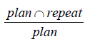 and DSC as
 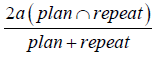 . OI was used to estimate the ratio of NNL volume in CTrep overlapped by that in CTplan. Both OI and DSC were between 0 and 1, and higher values indicate good overlap. Because of the high false impression of high agreement (21,24), both OI and DSC might provide more complementary information to estimate the NNL overlap during the treatment course.
Contour surface-based analysis could aid in the visualization of areas of disagreement and could be valuable for estimating the contour variability of inter-observer and in multi-images (21,23). The shortest perpendicular distance (SPD) (19) could be used to estimate the accuracy of delineation and contour variability. SPD was computed from two delineated NNL surfaces in CTplan and CTrep. In each point of the NNL surface in the CTplan along its perpendicular direction, another close point in CTrep could be calculated automatically and the distance between these two points was defined as SPD (18,19). The mean and SD for SPD were used to present the surface variability.
Margin for NNLs
For each NNL, to estimate the expanded PTV margin, the isotropic margins with 1, 2, 3, 4, and 5 mm around the NNL in the CTplan were expanded outward to establish the PTV_NNL. PTV_NNL was compared with NNL in each repeat CT and then OI could be calculated. The lower limit of the 90% confidence interval was higher than 0.95 and was arbitrarily defined as the acceptable geometrical coverage (18,22).
Statistical analysis
One-way analyses of variance and chi-square tests were used to compare volume, DSC, and mean SPD across weeks. For all statistical tests, two-tailed and a 5% significance level were used when establishing statistical significance. The Statistical Package for Social Sciences (SPSS version 20.0; IBM Corporation, Armonk, NY, USA) was used for all analyses.
Results
Distribution of LNs in NNLs and the radiation dose delivered
In this study, the LNs with the minimal diameter longer than 1.0 cm were arbitrarily defined as positive neck LNs. Totally, 22 and 28 LNs were positive in the left- and right-sided neck, respectively (Table 1). In the left-sided LNs, 85% were in level II and 15% were in level III. In the right-sided LNs, 95% and 20% were in level II and III, and 5% and 10% were in level IV and V, respectively (Table 1). There were no positive LNs in levels IA, IB, and VI on both sides, and no positive LNs in the left level IV and V. The radiation dose delivered to each NNL is shown in Table 1.

Full table
Volume variations
All the NNLs (not including level IA) showed linear time trend throughout treatment (Figure 1). In level IA, the volume reduced by 5.6% at the end of the 1st week and increased by 0.5–4.3% thereafter. The volume of level IB reduced by 6.4% after the first week and by 21.2% at the end of the sixth week. The other NNLs showed smaller volume reductions. For levels II–IV, the average volume reduction ranged from 6.1% to 9.9%, as shown in Table 2.


Full table
Positional displacement
For all the NNLs, the systematic errors were 0.2–1.0 mm, 0.2–0.6 mm, and 0.2–0.8 mm in the LR, AP, and CC directions, respectively (Table 3). Generally, levels IB and II had smaller systematic error than the other NNLs. Random error was less than 1.0 mm in all the directions in level IB, II, and III. It was larger than 1.0 mm in all the directions in levels V and VI. Moreover, the three-dimensional vector displacements were <2.0 mm in levels IB and II, 2.1–3.9 mm in levels III and IV, 3.1–3.6 mm in levels IA and VI, and 5.1 mm in level V. The displacements in the LR direction had no significant difference between the left- and right-sided NNLs (Figure 2).

Full table

Shape changes
Both the OI and DSC showed decreasing time trends as increasing radiation fractions were delivered. For levels IB, II, and III, OI could be maintained higher than 0.7 throughout the treatment course, yet for levels IA, V, and VI, it was <0.7 after the 2nd week (Table 4). DSC had a similar time trend to OI. However, DSC in level V was lower than 0.7 throughout the treatment course. SPD standard deviation showed increasing time trends (Table 4). The mean SPD for all NNLs, except level V, ranged from 1.7 to 2.1 mm and that of level V was 3.1±1.4 mm. Moreover, the SPD in level IA–IV was 2.2–2.8 mm and those in level V and VI were 3.8±1.4 and 3.2±1.2 mm, respectively.

Full table
Expanded margins
For all NNLs, to maintain acceptable coverage during the whole treatment course, the OI of the PTV_NNL and NNL in CTrep should be higher than 90% throughout treatment. For NNL IB, II and III, the minimal margin needed was 2 mm. For NNL IV, it was 3 mm, for NNL V and VI the margin needed was 4 mm, and for NNL IA and, it was 5 mm due to the generous position variations of the jaw (Figure 3).

Discussion
In this case-cohort study, 20 patients with NPC had 140 CT scans throughout IMRT course. By mimicking weekly image-guided radiotherapy (IGRT), we quantitatively analyzed the geometrical change of each NNL. For most NNLs, the volume and shape changes had linear time trends. The 3D vector displacement of all NNLs was 1.5–5.1 mm. To maintain an acceptable geometrical coverage, each NNL should have an individualized margin of 2–5 mm. These findings might be useful for the further optimization of radiation therapy for NPC.
Geometrical change
Several studies (3,4,25) quantified the volume and/or positional changes of the primary tumor and metastatic neck LNs in patients with head and neck squamous cell cancer and suggested that the volume of tumors and targets decreased and their positions were displaced considerably. For head and neck cancer, the volume reduction of middle-low risk clinical target volumes including most NNLs was 7.1–10.7% and the radiation dose increased substantially (26). However, the volume changes of level IA did not show the time-trend as the others did, which this discrepancy might be partially attributed to the variable positions of the jaw in each repeat CT scanning.
In this study, the average volume reduction for level II–VI was 6.1–9.9%. Studies by Tan et al. (18) and Hamming-Vrieze et al. (6) showed that the tumor shape estimated by the tumor surface distance changed significantly and the mean SPD was 2.2–4.6 mm (6,18). In the present study, the surface distance was 1.7–3.1 mm for all NNLs. Anatomically, the body surface in the head and neck changes substantially from the upper to the lower neck. During RT for head and neck cancer, the brain, neck, and shoulders are usually immobilized with a 5-point mask and three lasers are used to maintain reproducibility. Therefore, it is reasonable that the daily position, especially for the sub-regions with large anatomical variations, did not match well.
Tumor shape variability depended on sub-localization and tumor volume (6), and the local geometrical uncertainties were quite different in anatomical sub-regions during RT for patients with head and neck cancer (27). Of the anatomical changes, tumor shrinkage did not comprise the radiation dose to the target volume, which might be due to the adequate PTV margin. The combination of replanning and reduced margin strategy for the parotid gland could provide approximately 30% dose sparing (8). In this study, the different geometric variability among the various NNLs suggested that more attention should be paid to the NNLs deformation, especially for NNL with positive LNs and even some NNLs such as levels IA, V, and VI.
Individualized Margin for each NNL
During planning and executing RT, many sources of error exist, limiting its accuracy. Therefore, a safety margin ensures that the planned dose is actually delivered to the target volume for almost all patients (22). IMRT is essentially preferred for NPC with better local control and survival, with reduced toxicity, and the PTV was based on the clinical target volume plus a 3–5 mm additional margin (28). However, in image-guided RT with weekly cone-beam CT, the PTV margin could be individualized by 1.3–3.0 mm in three directions (29). All these recommendations usually consider the locoregional tumors and all the elective NNLs as an entirety, while ignoring the large anatomical deformation in the head and neck as well as the considerable geometrical changes throughout the treatment course.
For head and neck cancer, substantial anatomical changes, position, and shape variability of the tumor might result from tumor regression and weight loss, which resulted in various geometrical and setup uncertainties (3,18). By limiting these uncertainties, the margin could be safely reduced, which might enable a better dose distribution in target and normal tissues and the improved clinical outcome (17). In our study, it seemed that a smaller margin could be safely used in levels IB, II, and III and that levels IA, VI, and V should have more generous margins even if the weekly image guided setup is correct. The larger geometrical variations in levels IB and II might be owing to the substantial shrinkage of the submandibular gland in these levels and that level II had a higher ratio of the positive LNs that shrunk substantially during treatment (4). Although levels IB and II have large volumetric reduction, they are located in the upper neck and could be well immobilized and matched during RT delivery and need smaller margins (<3 mm). Level IA needs ~5 mm margin because the jaw had poor reproducibility, especially in patients with more weight loss. Level V needs 5 mm margins because of large neck surface variation and larger inter-fractional motion of the shoulders (16,17). Although level VI had a small volumetric reduction, it needed a more generous margin because of substantial deformation in the anterior part of the neck, which probably resulted from the re-distribution of subcutaneous fat and thyroid shrinkage. Moreover, for a single NNL, the margin might be individualized with/without positive LNs.
The margin could not solely depend on geometrical uncertainties. Rather, it should consider global patient setup accuracy, correction strategies, margin design, and anatomical deformations. In head and neck cancer patients with offline correction, the local setup variations were proven to exceed residual global patient setup uncertainty (27). In this study, the local anisotropic margins of each NNL were required, and for all NNLs, the clinically applied isotropic margin of 3–5 mm may be enough to correct the anatomical deformation during RT. However, if the daily set-up and target delineation are taken into account, the recommended margin seemed inadequate.
Adaptive re-planning
During treatment, changes in the tumors and normal structures (3,4) might result in the substantial dosimetric distribution differences between the planning and delivered doses (8). Through online or off-line interventions at different times, adaptive radiation therapy (ART) is used to correct for temporal morphological changes in a patient’s anatomy during IMRT (2,30). Replanning during treatment might be one feasible method (2). However, the optimal timing and the definition of volumes had little consensus (26). In previous studies, adaptive correction was suggested in the early stage of treatment, as it might be potentially feasible (4,18). Recently, Hamming-Vrieze et al. (31) suggested that CTV reduction in mid-treatment could potentially decrease the radiation dose to OAR and the gross target volume adjustment according to clear anatomical boundaries might be safe. In our study, all the NNLs were defined by the spatially determined anatomical boundaries, and the re-delineation of the NNLs during RT seemed to not compromise the radiation to the target and had dose-sparing effects for OAR.
Limitations
In this study, we quantified the geometrical changes of each NNL during RT for NPC, which might be useful to estimate the individually expended margin for the neck subregions in the planning design and adaptively correct the anatomical deformation during RT. However, several limitations of this study should be addressed. Firstly, the geometrical variations were analyzed but we did not cover the changes to the radiation dose delivered to NNLs and the dose distribution differences in RT with and without adaptive corrections. Secondly, the repeat CT in this study was to obtain the anatomical deformation during RT. The CTrep and CTplan were registered without deformation correction, which is similar to the daily clinical practice seen in image-guided RT. However, repeat CT image quality might be better than that currently used in clinics, such as cone-beam CT, which might mitigate the inaccuracy of registration and under-estimate the anatomical variations and the required margin. Thirdly, during RT preparation and execution, the design of margins should remove all uncertainties, such as the limited imaging quality, delineation uncertainty, setup inaccuracy, and organ motion. In this study, only anatomical variations were included and the aforementioned factors were not covered. Therefore, the recommended margins should be larger than that in our study, as was done previously (27). In addition, the anisotropic margin might be more reasonable. Lastly, the updated NNL delineation guideline (13) increases a few new levels that were not included in our study. And geometrical variation and margin of the new NNLs might be extrapolated from the near sub-regions. Despite these drawbacks, our study remains useful for the optimization of RT for NPC, even for head and neck cancer.
Conclusions
We quantified the geometrical variations of each NNL for NPC and estimated the margin needed to maintain geometrical coverage during RT, which suggested that the individualized NNL margin could be more reasonable and feasible. The volume of all NNLs, except IA, reduced by 6.1–15.1% on average and the 3D vector displacements of NNLs were 1.5–5.1 mm. Levels IB, II, and III had small positional displacements, which need a smaller margin of 2–3 mm. Yet, for levels IA, VI, and V had large ones, which need an individual margin with 4–5 mm to maintain geometrical coverage. This quantitative geometrical variation of NNLs will facilitate adaptive strategies for NPC. However, the changes of dose distribution in NNLs and optimal adaptive adjustment strategies need further study.
Acknowledgements
We are grateful to Prof. Jan-Jakob Sonke from the Department of Radiation Oncology, The Netherlands Cancer Institute, Amsterdam, The Netherlands, who generously offered the research software (WRLDMATC) developed in-house for this research. We would like to thank Editage Inc. for careful English proofreading.
Funding: This work was funded by Sanming Project of Medicine in Shenzhen (SZSM201612023) and Shenzhen Clinical Research Funding (SZLY2018008).
Footnote
Conflicts of Interest: This work was presented at the 57th annual meeting of the American Society of Radiation Oncology, San Antonio, Texas, USA, October 18 - 21, 2015.
Ethical Statement: This study was approved by the research ethics committee, Hubei Cancer Hospital.
References
- Lee AW, Ng WT, Chan YH, Sze H, Chan C, Lam TH. The battle against nasopharyngeal cancer. Radiother Oncol 2012;104:272-8. [Crossref] [PubMed]
- Castadot P, Lee JA, Geets X, Gregoire V. Adaptive radiotherapy of head and neck cancer. Semin Radiat Oncol 2010;20:84-93. [Crossref] [PubMed]
- Barker JL Jr, Garden AS, Ang KK, O'Daniel JC, Wang H, Court LE, Morrison WH, Rosenthal DI, Chao KS, Tucker SL, Mohan R, Dong L. Quantification of volumetric and geometric changes occurring during fractionated radiotherapy for head-and-neck cancer using an integrated CT/linear accelerator system. Int J Radiat Oncol Biol Phys 2004;59:960-70. [Crossref] [PubMed]
- Tan W, Li Y, Han G, Xu J, Wang X, Li Y, Hu D. Target volume and position variations during intensity-modulated radiotherapy for patients with nasopharyngeal carcinoma. Onco Targets Ther 2013;6:1719-28. [Crossref] [PubMed]
- Castadot P, Geets X, Lee JA, Christian N, Gregoire V. Assessment by a deformable registration method of the volumetric and positional changes of target volumes and organs at risk in pharyngo-laryngeal tumors treated with concomitant chemo-radiation. Radiother Oncol 2010;95:209-17. [Crossref] [PubMed]
- Hamming-Vrieze O, van Kranen SR, van Beek S, Heemsbergen W, van Herk M, van den Brekel MW, Sonke JJ, Rasch CR. Evaluation of tumor shape variability in head-and-neck cancer patients over the course of radiation therapy using implanted gold markers. Int J Radiat Oncol Biol Phys 2012;84:e201-7. [Crossref] [PubMed]
- Brouwer CL, Steenbakkers RJHM, Langendijk JA, Sijtsema NM. Identifying patients who may benefit from adaptive radiotherapy: Does the literature on anatomic and dosimetric changes in head and neck organs at risk during radiotherapy provide information to help? Radiotherapy and Oncology 2015;115:285-94. [Crossref] [PubMed]
- Wu Q, Chi Y, Chen PY, Krauss DJ, Yan D, Martinez A. Adaptive replanning strategies accounting for shrinkage in head and neck IMRT. Int J Radiat Oncol Biol Phys 2009;75:924-32. [Crossref] [PubMed]
- Wang X, Hu C, Ying H, He X, Zhu G, Kong L, Ding J. Patterns of lymph node metastasis from nasopharyngeal carcinoma based on the 2013 updated consensus guidelines for neck node levels. Radiother Oncol 2015;115:41-5. [Crossref] [PubMed]
- Lang J, Gao L, Guo Y, Zhao C, Zhang C. Society of H, Neck Tumor S, Society of Radiation T, Chinese Anti-Cancer A. Comprehensive treatment of squamous cell cancer of head and neck: Chinese expert consensus 2013. Future Oncol 2014;10:1635-48. [Crossref] [PubMed]
- Gregoire V, Levendag P, Ang KK, Bernier J, Braaksma M, Budach V, Chao C, Coche E, Cooper JS, Cosnard G, Eisbruch A, El-Sayed S, Emami B, Grau C, Hamoir M, Lee N, Maingon P, Muller K, Reychler H. CT-based delineation of lymph node levels and related CTVs in the node-negative neck: DAHANCA, EORTC, GORTEC, NCIC,RTOG consensus guidelines. Radiother Oncol 2003;69:227-36. [Crossref] [PubMed]
- Gregoire V, Eisbruch A, Hamoir M, Levendag P. Proposal for the delineation of the nodal CTV in the node-positive and the post-operative neck. Radiother Oncol 2006;79:15-20. [Crossref] [PubMed]
- Gregoire V, Ang K, Budach W, Grau C, Hamoir M, Langendijk JA, Lee A, Le QT, Maingon P, Nutting C, O'Sullivan B, Porceddu SV, Lengele B. Delineation of the neck node levels for head and neck tumors: a 2013 update. DAHANCA, EORTC, HKNPCSG, NCIC CTG, NCRI, RTOG, TROG consensus guidelines. Radiother Oncol 2014;110:172-81. [Crossref] [PubMed]
- Cheo T, Loh Y, Chen D, Lee KM, Tham I. Measuring radiotherapy setup errors at multiple neck levels in nasopharyngeal cancer (NPC): A case for differential PTV expansion. Radiother Oncol 2015;117:419-24. [Crossref] [PubMed]
- Zhang S, Zhou X, Zhang Q, Jiang S, Wang R, Zhang G, Lei H, Lin S. Analysis of setup error based on CTVision for nasopharyngeal carcinoma during IGRT. J Appl Clin Med Phys 2016;17:15-24. [Crossref] [PubMed]
- Neubauer E, Dong L, Followill DS, Garden AS, Court LE, White RA, Kry SF. Assessment of shoulder position variation and its impact on IMRT and VMAT doses for head and neck cancer. Radiat Oncol 2012;7:19. [Crossref] [PubMed]
- Casey KE, Wong PF, Tung SS. Effect of interfractional shoulder motion on low neck nodal targets for patients treated using volumetric-modulated arc therapy (VMAT). J Appl Clin Med Phys 2015;16:40. [Crossref] [PubMed]
- Tan W, Ye J, Xu R, Li X, He W, Wang X, Li Y, Hu D. The tumor shape changes of nasopharyngeal cancer during chemoradiotherapy: the estimated margin to cover the geometrical variation. Quantitative Imaging in Medicine and Surgery 2016;6:115-24. [Crossref] [PubMed]
- Zhang H, Tan W, Sonke J-J. Effect of compressed sensing reconstruction on target and organ delineation in cone-beam CT of head-and-neck and breast cancer patients. Radiotherapy and Oncology 2014;112:413-7. [Crossref] [PubMed]
- Kron T, Thomas J, Fox C, Thompson A, Owen R, Herschtal A, Haworth A, Tai KH, Foroudi F. Intra-fraction prostate displacement in radiotherapy estimated from pre- and post-treatment imaging of patients with implanted fiducial markers. Radiother Oncol 2010;95:191-7. [Crossref] [PubMed]
- Fotina I, Lutgendorf-Caucig C, Stock M, Potter R, Georg D. Critical discussion of evaluation parameters for inter-observer variability in target definition for radiation therapy. Strahlenther Onkol 2012;188:160-7. [Crossref] [PubMed]
- van Herk M. Errors and margins in radiotherapy. Semin Radiat Oncol 2004;14:52-64. [Crossref] [PubMed]
- Heimann T, Meinzer HP. Statistical shape models for 3D medical image segmentation: a review. Med Image Anal 2009;13:543-63. [Crossref] [PubMed]
- Castadot P, Lee JA, Parraga A, Geets X, Macq B, Gregoire V. Comparison of 12 deformable registration strategies in adaptive radiation therapy for the treatment of head and neck tumors. Radiother Oncol 2008;89:1-12. [Crossref] [PubMed]
- Wang RH, Zhang SX, Zhou LH, Zhang GQ, Yu H, Lin XD, Lin S. Volume and dosimetric variations during two-phase adaptive intensity-modulated radiotherapy for locally advanced nasopharyngeal carcinoma. Biomed Mater Eng 2014;24:1217-25. [PubMed]
- Veresezan O, Troussier I, Lacout A, Kreps S, Maillard S, Toulemonde A, Marcy PY, Huguet F, Thariat J. Adaptive radiation therapy in head and neck cancer for clinical practice: state of the art and practical challenges. Jpn J Radiol 2017;35:43-52. [Crossref] [PubMed]
- van Kranen S, van Beek S, Rasch C, van Herk M, Sonke JJ. Setup uncertainties of anatomical sub-regions in head-and-neck cancer patients after offline CBCT guidance. Int J Radiat Oncol Biol Phys 2009;73:1566-73. [Crossref] [PubMed]
- Lee AW, Lin JC, Ng WT. Current management of nasopharyngeal cancer. Semin Radiat Oncol 2012;22:233-44. [Crossref] [PubMed]
- Su J, Chen W, Yang H, Hong J, Zhang Z, Yang G, Li L, Wei R. Different setup errors assessed by weekly cone-beam computed tomography on different registration in nasopharyngeal carcinoma treated with intensity-modulated radiation therapy. Onco Targets Ther 2015;8:2545-53. [PubMed]
- Schwartz DL. Current progress in adaptive radiation therapy for head and neck cancer. Curr Oncol Rep 2012;14:139-47. [Crossref] [PubMed]
- Hamming-Vrieze O, van Kranen SR, Heemsbergen WD, Lange CAH, van den Brekel MWM, Verheij M, Rasch CRN, Sonke JJ. Analysis of GTV reduction during radiotherapy for oropharyngeal cancer: Implications for adaptive radiotherapy. Radiother Oncol 2017;122:224-8. [Crossref] [PubMed]

