
Exploration of highly accelerated magnetic resonance elastography using high-density array coils
Introduction
For centuries, physicians have relied on palpation as a means of qualitatively assessing states of diseases, however this is not possible for internal organs. Recently, magnetic resonance elastography (MRE) has provided a non-invasive quantitative means of assessing tissue stiffness by applying a transverse shear wave to a sample or patient in the presence of a motion sensitizing gradient (1) and observing its local wavelength. This has allowed the calculation of the local shear modulus (2), often in areas inaccessible to palpation, finding applications in the liver, breast, brain, skeletal muscle, and heart (3,4). Another approach called mechanical transient-based MRE assesses tissue stiffness by monitoring the propagation of a wave front through a sample, requiring additional time steps, usually resulting in longer scan times (5). MRE has also been used in the study of dynamic processes, such as monitoring of thermal ablation (6). Several avenues have been pursued to improve the speed of MRE, such as using spatially selective excitations (7), or using one-dimensional projections for monitoring ultrasound therapy (8) and in vivo muscle stiffness (9). Additionally, alternative acquisition strategies such as fractional encoding (10), and sample interval modulation (SLIM)-MRE (11) have been investigated. There have also been a number of in vitro or other non-clinical applications, particularly using microscopic MRE (µMRE) to construct elastograms at higher resolutions, which has been used for frog oocytes (12), in tissue engineering (13), and in the study of traumatic brain injury models (14).
Parallel imaging using RF coils and gradient-based echo planar imaging have significantly improved acquisition times, extending the possibilities of functional MRI. Our group has previously used arrays of long parallel planar receive coils for highly accelerated MRI. This has enabled single echo acquisition (SEA) imaging (15), in which each MR image is acquired in one echo, as well as highly accelerated MR microscopy over an extended field of view (FOV) (16). Applications such as turbulent flow (17) and microscopy of excised brain slices have been investigated. The system was further extended to facilitate imaging of thicker volumes using a biplanar receive array and an insertable x-, y-gradient coil to compensate for the phase gradient due to the RF coil elements (18). Combined with strong and fast gradients, imaging at 1,000 frames per second has been shown (19). This paper presents some of our initial exploration of MRE using highly parallel receive array coils over a range of spatio-temporal acquisition regimes, from ultra-fast SEA to highly accelerated high resolution imaging. Applications of interest include accelerated mechanical-transient based MRE, MRE during thermal ablation or other destructive tests, and µMRE over an extended FOV.
Methods
MRE of agar phantoms was performed at 4.7T using a Varian Unity INOVA imaging spectrometer. Uniplanar and biplanar receive arrays were used, with an insertable custom phase compensation gradient coil used with the biplanar array. A 64 channel receiver system, built in-house, was used for demodulation and data acquisition for both SEA and highly accelerated, high resolution imaging. In SEA, phase encoding is completely eliminated, with spatial localization along the array elements replaced by the confined B1 patterns of the individual coil elements. RF excitation was accomplished using a custom parallel plate volume coil similar to that described by Marshall et al. (20). A sinusoidal x-gradient pulse at the same frequency as the applied vibration was added to a standard spin echo pulse sequence to provide motion sensitization. An analog output card controlled by a LabVIEW script (National Instruments, Austin, TX, USA) and triggered by the Varian spectrometer was used to generate the vibration signal, which was then amplified and connected either to an electromechanical actuator or to a speaker driving a pneumatic actuator via flexible tubing (21).
Processing of the data to extract MRE “wave images” from subtraction of phase images was performed offline using MATLAB (The MathWorks, Natick, MA, USA). Except for the heating measurements described below, phase subtractions using a single reference image acquired with the actuator disabled yielded sets of frames showing propagation of the transverse shear waves. The use of a reference phase image allowed for correction for any variations between channels due to the array coil or acquisition system. For SEA imaging, phase subtraction was done on a coil-by-coil basis, subtracting the phase angle of the 1D projection from each array element from the reference phase projection taken from the same coil. These phase difference projections were stacked in a matrix, giving a 2D wave image over the surface of the array. In high resolution imaging, the fully encoded sub-images from each array element were processed into 2D wave images via phase subtraction. Following a procedure similar to PILS (22), a rectangular window was applied to the phase subtraction image of each coil and these sub-images were stacked in a matrix covering the entire FOV of the array. For a sinusoidal motion sensitizing gradient of amplitude G0 and N periods, each of duration T, the magnitude of the phase accrued by each voxel, ϕ0, due to cyclic motion of each isochromat with peak displacement ξ0 is given by
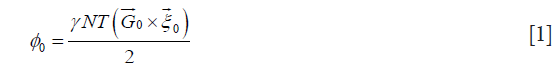
which allows calculation of quantitative displacement maps from the phase images.
Uniplanar array
Imaging with a uniplanar receive array coil was performed in a 33-cm magnet with a GE Acustar gradient coil and Techron 8600 amplifiers, with a TR of 3 s and TE of 30 ms. The long TR allowed the vibration to die out before the next acquisition. A 13 cm × 8.1 cm array of 64 planar pair coil elements, each 2 mm wide (23) was used to acquire SEA MRE wave images of a 10.3 cm × 7.5 cm phantom consisting of two concentrations of agar placed side by side, with the stiffer agar on the top as shown in Figure 1A. An acrylic plate was embedded in the agar and attached to an electromechanical actuator by a pivoting rod, with a bipolar 200 Hz x-gradient pulse used for motion sensitization. The time delay of the actuator was stepped by 138.8 µs upon each acquisition, corresponding to 10 degrees of the 200 Hz vibration. A small volume of agar was also placed over several array elements adjacent to the sample, serving as a stationary reference for correcting phase differences between the Varian scanner and the acquisition system. For harmonic MRE, eight periods (40 ms) of a 200 Hz vibration was applied to the sample. The wavelength was estimated by the distance between crests of the shear wave in the sample, which allowed calculation of the velocity of propagation. For transient MRE, a single period of a 200 Hz sine wave was supplied to the actuator. This allowed capture of the mechanical wave front as it propagated into and throughout the sample, allowing estimation of the velocity of propagation by following the wave front through successive frames. A rough estimation of shear stiffness was computed using


where is the shear stiffness, is the velocity of propagation, and is the density, assumed as 1 g/cm3 (5).
Uniplanar array combined with a local heat source
An identical experimental setup was constructed with a uniform agar concentration (125 mL 0.1 g/L hydrated CuSO4 and 0.9 g of agar) for harmonic MRE measurements during heating. Thermal energy was derived from a standard 50 W/12 V halogen lamp, connected in series with two 1 Ω non-inductive resistors, needed to reduce the current and resulting force due to the magnetic field. The lamp was fixed 1 cm above the surface of the gel using a mechanical fixture, with location indicated in Figure 1B. The 200 Hz vibration source was activated 10 ms prior to the execution of the pulse sequence ensure that there were several shear waves in the gel during motion encoding, while not allowing standing waves due to reflections from the phantom walls. The vibrations were maintained for 30 ms or 6 time periods.
Because of physical changes in the phantom and its phase map due to heating, a single initial scan no longer provided an adequate phase reference for subtraction. Instead, each MRE wave image frame was constructed from a pair of phase images acquired using SEA with bipolar motion sensitizing gradient pulses of opposite amplitude. A 500 ms delay between acquisitions allowed the shear waves from the first acquisition to completely attenuate before the second acquisition began. This time was kept short to limit any heating between the acquisitions.
Biplanar array
Imaging using a biplanar or “sandwich” receive array to extend the FOV along the y direction was performed in a 40-cm magnet with a BFG 400/260 gradient coil (Resonance Research, Inc., Billerica, MA, USA) and QDCM1400 amplifiers (Performance Controls, Inc., Montgomeryville, PA, USA) with a TE of 30 ms. Two 65 mm × 70 mm arrays, each with 32 2-mm elements were employed to acquire MRE wave images from a 1% agar phantom approximately 1 cm thick and spanning the dimensions of the array, shown in Figure 2. A small “inclusion” with half the agar concentration of the surrounding material was also embedded to provide a region of slower velocity of propagation and shorter wavelength. Vibrations were supplied to the sample at 400 Hz via a pneumatic actuator, relying on mode conversion from the applied longitudinal waves to transverse shear waves (24). Motion sensitization was provided by a 400 Hz sinusoidal bipolar pulse added to the x-gradient at 11.72 G/cm. The time delay of the actuator was stepped by 125 µs upon each acquisition with a TR of 1 s. A spin echo pulse sequence, shown in Figure 3, was modified to include a custom 90º RF pulse which simultaneously excited two 0.75 mm slices separated by 7.5 mm for SEA imaging near the lower and upper surfaces of the sample. The slice selection gradient was disabled during the 180º pulse, allowing a standard sinc pulse to refocus both slices. Additional spoiling time was added to the frequency encoding gradient to mitigate the effect of stimulated echoes. The same biplanar array was used for highly accelerated high resolution MRE, with two 1-mm thick slices separated by 8.5 mm excited simultaneously and imaged using a 1.5 s TR. Five hundred twelve frequency encoding points and 64 phase encoding steps were employed for reduced FOV imaging from each array element (80 mm × 8.0 mm). These sub-images were assembled to form a high resolution image over the FOV of the entire array with voxel sizes of 156 µm × 125 µm.


Insertable phase compensation gradient coil
Because the voxels in SEA imaging and some highly accelerated acquisition strategies are comparable to the dimension of the RF coils, the RF phase gradient due to the B1 pattern of the coil elements can result in significant signal cancellation. This can be understood as an offset in the center of k-space due to the RF coil phase gradient (25). In SEA, a “phase compensation” gradient pulse is used to impart a linear phase gradient across the voxels to counter the effect of the B1 phase gradient (15). With uniplanar arrays, this is accomplished by a brief pulse of the system gradient across the narrow dimension of the array coil elements. However, the B1 phase gradient varies with distance from the array and reverses sign depending on whether the array is placed above or below the sample, preventing SEA and highly accelerated imaging using both arrays simultaneously. To overcome this, an insertable biplanar nonlinear (x-, y-) gradient coil, shown in Figure 4, was employed to provide opposite phase compensation for both arrays (18). This coil was designed using a target field approach to produce a linear x-gradient, which also varies linearly in y. It is called a “nonlinear” gradient coil to differentiate it from the normal imaging gradients. The strength and duration of the gradient pulse are selected to achieve the desired phase gradient reversal depending on the coil element geometry and separation between the top and bottom arrays. For this biplanar array, the compensation gradient, denoted Gcomp in Figure 3, was configured for ±8.0 rad/cm over a 1 cm slab. An additional pulse may be added to the x-gradient axis to offset the location of the phase reversal plane if the sample is not centered vertically within the insertable gradient coil. Phase compensation was not necessary for the high resolution MRE images due to the smaller voxel sizes and less significant B1 phase gradient across each voxel.

Results
Uniplanar array
Individual SEA MRE “wave images” from the harmonic and transient acquisitions using the uniplanar array are shown in Figures 5 and 6, respectively. In both scans, a total of 720 frames were acquired at a rate of one image per echo. In these images, a longer TR of 3 s was used to ensure damping of vibrations from the previous excitation, yielding a total scan time for each data set of 36 min. While use of a shorter TR would decrease the scan time, the use of recalled echoes could provide much greater acceleration, as discussed in the next section. The images show the wave front entering and propagating across the sample. Some bulk motion of the sample is also visible in the images. From the harmonic MRE experiment, the local wavelength in the upper half of the agar with double concentration was 2.4 cm, yielding velocity and shear stiffness estimates of 4.8 m/s and 23 kPa. In the lower region, the wavelength was 1.1 cm, yielding velocity and shear stiffness estimates of 2.2 m/s and 5 kPa. From the frames of the transient acquisition shown in Figure 6, the velocity in the upper half was approximately 4.0 m/s, while the velocity in the lower half was 2.9 m/s, yielding shear stiffness estimates of 16 and 8 kPa, respectively.


Uniplanar array combined with a local heat source
A set of 2,950 MRE wave images (processed from 5,900 motion encoded image pairs) were obtained using SEA to capture harmonic transverse shear waves in the agar gel phantom as it was heated and subsequently cooled with each frame spaced by 2.5 s. Although the frames could have been captured at much higher temporal resolution, an interval of 2.5 s was adequate to capture changes caused by the low powered heating source. The 2,950 MRE wave images are classified into three zones. Zone I consists of the first 100 frames (250 s) obtained at room temperature. This allowed verifying the system stability and quantification of measurement errors. Zone II has 950 frames collected during heating (2,375 s), while Zone III was acquired with the warm gel cooling down, over a time period of 4,750 seconds. MRE images in Figure 7 depict the changing wavelength of the shear waves as time progressed and the gel grew warmer in Zone II and also as the gel cooled down in Zone III. Figure 8 shows the calculated wavelength of the shear waves during gel heating and cooling.


Biplanar array
SEA MRE wave image pairs acquired simultaneously from the bottom and top boundaries of the agar sample using the biplanar receive array and insertable phase compensation gradient are shown in Figure 9. The set of 240 time steps was acquired in 4 min, although this could have been reduced using a shorter TR, provided that the vibrations are allowed to decay between acquisitions. The frames were processed into quantitative displacement maps, indicating peak displacements of around ±25 µm. An emerging shear wave with notably shorter wavelength in the half-concentration agar inclusion in the upper right area of the images is visible. Because this inclusion was recessed somewhat from the top surface of the sample, there is a regional signal void in the frames captured from the top array. The same set of 240 time steps was acquired at a resolution of 156 µm × 125 µm × 1,000 µm using the same array, except with a TR of 1.5 s for a total scan time of 6.4 h. The TR was increased slightly to allow the acquisition system additional time to demodulate and store the data. Both of these limitations are discussed in the next section. While two slices were simultaneously excited and acquired for a total acceleration factor of 20, the gel had receded somewhat from the top array preventing reconstruction of the top images. While averaging is usually required for high resolution magnetic resonance imaging (MRI), the need was mitigated by the reduced noise detected by each array element. One frame of the high resolution MRE data set along with four additional sub-frames from the soft agar region is shown in Figure 10. When viewed as an animation, the emerging wave front can be discerned, while more complex wave motion in the half-concentration inclusion is apparent.


Conclusions
While the acquired wave images were not processed into quantitative shear stiffness maps, a few of the possibilities of using high density receive arrays for both high speed and high resolution MRE were explored. The TR on the order of 1–3 s employed in these scans, which determines the frame rate of SEA imaging, was selected to ensure that all vibration from the previous acquisition had ceased before introducing a new vibration with the next stepped time offset. Despite this, scan times for multi-frame acquisitions were significantly reduced, which may be helpful when it is necessary to acquire many temporal offsets such as for transient MRE or in MRE of dynamic processes. As SEA has been demonstrated at one thousand frames per second using recalled echoes (19), a future area of interest is to apply this to MRE. By adjustment of the timing parameters, it has been shown that the motion sensitization inherent in the imaging gradients can also encode MRE (26). Extending this to SEA imaging would allow multiple images in each pulse train, allowing capture of several temporal offsets of a single wave front as it propagates across a sample. This will be further be enabled by a new, faster data acquisition system recently installed in the lab, which will reduce the need to use the longer TRs for data transfer and manipulation required by the system used in these studies. Together, these improvements would reduce the need for gated acquisitions with stepped temporal offsets and could be important for destructive or other non-repeatable testing. Another consideration in high speed MRE is the time required for motion encoding, resulting in temporal averaging of the shear wave position. At low frequencies, even a single bipolar gradient pulse will effectively average the wave motion over several milliseconds, which may be overcome through faster encoding. High resolution MRE presents the additional challenge that the resolution of the final elasticity maps are limited by the wavelength of the acoustic wave in the sample, and therefore by the acoustic driving frequency (27). Higher frequency acoustic waves not only require faster gradient switching, but their attenuation is also higher, limiting the FOV. It is hopeful that these and other challenges can be addressed through new acquisition strategies, in which high-channel-count and high-density arrays may play a part.
Acknowledgements
Funding: This work was partially supported by the NIH (1R21EB005695, 1R21EB007649).
Footnote
Conflicts of Interest: The authors have no conflicts of interest to declare.
References
- Muthupillai R, Rossman PJ, Lomas DJ, Greenleaf JF, Riederer SJ, Ehman RL. Magnetic resonance imaging of transverse acoustic strain waves. Magn Reson Med 1996;36:266-74. [Crossref] [PubMed]
- Manduca A, Oliphant TE, Dresner MA, Mahowald JL, Kruse SA, Amromin E, Felmlee JP, Greenleaf JF, Ehman RL. Magnetic resonance elastography: Non-invasive mapping of tissue elasticity. Med Image Anal 2001;5:237-54. [Crossref] [PubMed]
- Mariappan YK, Glaser KJ, Ehman RL. Magnetic resonance elastography: a review. Clin Anat 2010;23:497-511. [Crossref] [PubMed]
- Glaser KJ, Manduca A, Ehman RL. Review of MR elastography applications and recent developments. J Magn Reson Imaging 2012;36:757-74. [Crossref] [PubMed]
- McCracken PJ, Manduca A, Felmlee J, Ehman RL. Mechanical transient-based magnetic resonance elastography. Magn Reson Med 2005;53:628-39. [Crossref] [PubMed]
- Wu T, Felmlee J. Assessment of thermal tissue ablation with MR elastography. Magn Reson Med 2001;45:80-7. [Crossref] [PubMed]
- Glaser KJ, Felmlee JP, Ehman RL. Rapid MR elastography using selective excitations. Magn Reson Med 2006;55:1381-9. [Crossref] [PubMed]
- Yuan L, Glaser KJ, Rouviere O, Gorny KR, Chen S, Manduca A, Ehman RL, Felmlee JP. Preliminary assessment of one-dimensional MR elastography for use in monitoring focused ultrasound therapy. Phys Med Biol 2007;52:5909-19. [Crossref] [PubMed]
- Bensamoun SF, Glaser KJ, Ringleb SI, Chen Q, Ehman RL, An K-N. Rapid magnetic resonance elastography of muscle using one-dimensional projection. J Magn Reson Imaging 2008;27:1083-8. [Crossref] [PubMed]
- Rump J, Klatt D, Braun J, Warmuth C, Sack I. Fractional encoding of harmonic motions in MR elastography. Magn Reson Med 2007;57:388-95. [Crossref] [PubMed]
- Klatt D, Yasar TK, Royston TJ, Magin RL. Sample interval modulation for the simultaneous acquisition of displacement vector data in magnetic resonance elastography: theory and application. Phys Med Biol 2013;58:8663-75. [Crossref] [PubMed]
- Othman SF, Xu H, Royston TJ, Magin RL. Microscopic magnetic resonance elastography (µMRE). Magn Reson Med 2005;54:605-15. [Crossref] [PubMed]
- Othman SF, Curtis ET, Plautz SA, Pannier AK, Butler SD, Xu H. MR elastography monitoring of tissue-engineered constructs. NMR Biomed 2012;25:452-63. [Crossref] [PubMed]
- Boulet T, Kelso ML, Othman SF. Microscopic magnetic resonance elastography of traumatic brain injury model. J Neurosci Methods 2011;201:296-306. [Crossref] [PubMed]
- Wright SM, McDougall MP. Single echo acquisition MRI using RF encoding. NMR Biomed 2009;22:982-93. [Crossref] [PubMed]
- McDougall MP, Wright SM. A parallel imaging approach to wide-field MR microscopy. Magn Reson Med 2012;68:850-6. [Crossref] [PubMed]
- Wright SM, McDougall MP, Bosshard JC. Progress in visualizing turbulent flow using single-echo acquisition imaging. Conf Proc IEEE Eng Med Biol Soc 2006;1:4877-80. [Crossref] [PubMed]
- Bosshard JC, McDougall MP, Wright SM. An insertable nonlinear gradient coil for phase compensation in SEA imaging. IEEE Trans Biomed Eng 2014;61:217-23. [Crossref] [PubMed]
- Wright SM, McDougall MP. MR Imaging at sub-millisecond frame rates. Proc Intl Soc Mag Reson Med 2009;17:259.
- Marshall EA, Listinsky JJ, Ceckler TL, Szumowski J, Bryant RG, Hornak JP. Magnetic resonance imaging using a ribbonator: Hand and wrist. Magn Reson Med 1989;9:369-78. [Crossref] [PubMed]
- Uffmann K, Ladd ME. Actuation systems for MR elastography: design and applications. IEEE Eng Med Biol Mag 2008;27:28-34. [Crossref] [PubMed]
- Griswold MA, Jakob PM, Nittka M, Goldfarb JW, Haase A. Partially parallel imaging with localized sensitivities (PILS). Magn Reson Med 2000;44:602-9. [Crossref] [PubMed]
- McDougall MP, Wright SM. 64-channel array coil for single echo acquisition magnetic resonance imaging. Magn Reson Med 2005;54:386-92. [Crossref] [PubMed]
- Yin M, Rouviere O, Ehman R. Shear wave diffraction fields generated by longitudinal MRE drivers. Proc Intl Soc Mag Reson Med 2005;13:2560.
- Jesmanowicz A, Froncisz W, Hyde JS. A complication in prescan strategy when using surface coils. Magn Reson Med 1987;5:318-22. [Crossref] [PubMed]
- Numano T, Mizuhara K, Hata J, Washio T, Homma K. A simple method for MR elastography: a gradient-echo type multi-echo sequence. Magn Reson Imaging 2015;33:31-7. [Crossref] [PubMed]
- Yasar TK, Royston TJ, Magin RL. Taking MR elastography (MRE) to the microscopic scale (µMRE). 2011 IEEE International Symposium on Biomedical Imaging: From Nano to Macro IEEE; 2011:1618-23.

